User Manual
Brightness Sensor
SKU: P-3RD-BS
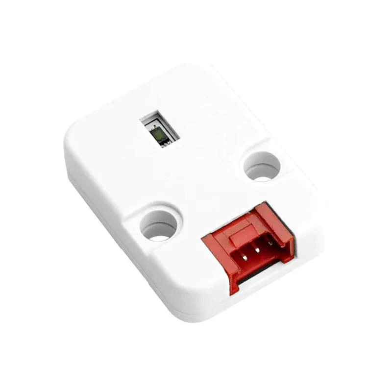
PIERRE brightness sensors are recommended, while compatible third-party sensors such as the BH1750 can also be used. The brightness sensor measures the ambient light level at its location, and this value can be used as a condition for lighting, blind, and other automations.
The sensor connects to the controller using a standard CAT6 cable.
It is configured in the PIERRE Partner application.
Keep the sensor cable separated from mains wiring.
For outdoor installations, use an outdoor-rated cable and suitable cable gland.
Switching or dimming lighting based on the actual light level instead of a fixed time.
Controlling blinds according to the amount of incoming light.
Switching outdoor lighting based on the actual daylight level, automatically adapting to seasonal changes.
Combining the light level with a schedule, motion sensor, or presence sensor to create more advanced automation conditions.
Sensor placement is important for accurate and reliable operation.
Do not point the sensor directly at a light source that it controls. This can create a feedback loop where the light switches on, the sensor detects the increased brightness, and the light switches off again.
For outdoor installations, mount the sensor facing north, away from direct sunlight and any controlled light source.
For more stable operation around dusk, use separate switch-on and switch-off thresholds to prevent the lighting from repeatedly switching on and off around a single light level.
Wired. Needs a PIERRE PRO or LITE Controller with two free Configurable I/O (digital) pins for SDA and SCL, plus the Brightness sensor (BH1750). The sensor takes 5 V from the controller.
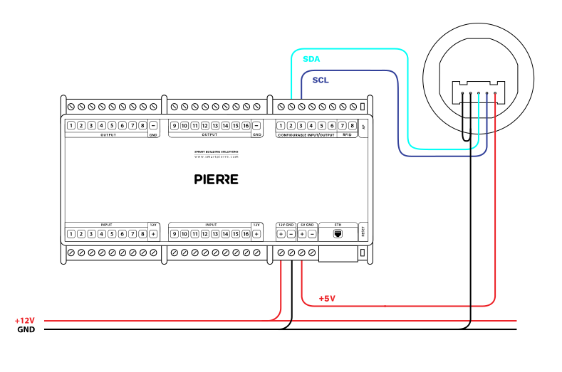
Wiring Compatible Brightness sensor in PIERRE smart home system - Electric schemes
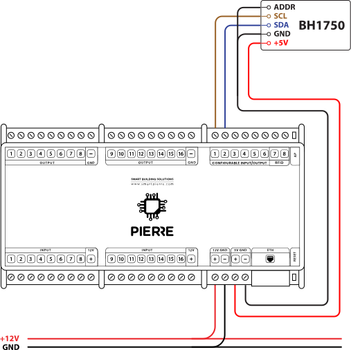
Brightness sensor BH1750 - Electric schemes
| Run | Wires | Cross-section | Cable type | Conductors |
|---|---|---|---|---|
| From BH1750 to PIERRE | 4 | 0.26 mm² (23 AWG) | Cat 6 S/FTP | +5 V, GND, SCL, SDA |
BH1750 brightness sensor: wiring and configuration, part 1. https://www.youtube.com/watch?v=gnYVwWbrPKE
BH1750 brightness sensor: wiring and configuration, part 2. https://www.youtube.com/watch?v=8VsVKJ817mc
Green – online and connected. Red – offline, no network or no internet. Light blue – AP mode, broadcasting its own network for setup. Dark blue – AP mode managed through PIERRE Partner. Purple – searching for an IP address from the router. Orange – downloading a firmware update.
Check that the sensor has been added to the configuration in the PIERRE Partner application.
Check GND, +5 V, SDA and SCL. The supply must be +5 V; reversed polarity damages the sensor.
Trace them with an acoustic wire detector and tone generator.
Connect it to GND.
Swap SDA and SCL.
No. Remove everything else and leave only the BH1750 on those Configurable I/O pins.
Measure between GND and +5 V at the sensor end. If there is no voltage, check the wiring.
15 m. For longer runs use a differential (I2C extender) module.
If one input influences an output, both should be added to the same controller. A motion sensor triggering a lamp, for example, performs best when both sit on the same controller.