Intercom Boston 8"
User Manual

Intercom Boston 8"

SKU: P-INT-BOSTON
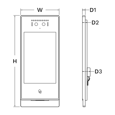
1. Product Size

Image
  • W: 130 mm
  • H: 308 mm
  • D1: 10.20 mm
  • D2: 16.50 mm
  • D3: 26.50 mm

2. Product Description

Image
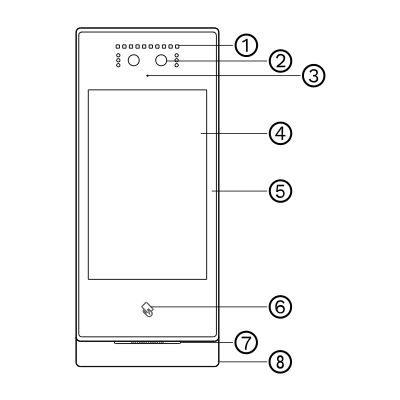
  1. Fill-in light
  2. Camera
  3. MIC
  4. Touch Panel
  5. Glass
  6. Card reader
  7. Speaker
  8. Aluminium frame
Image
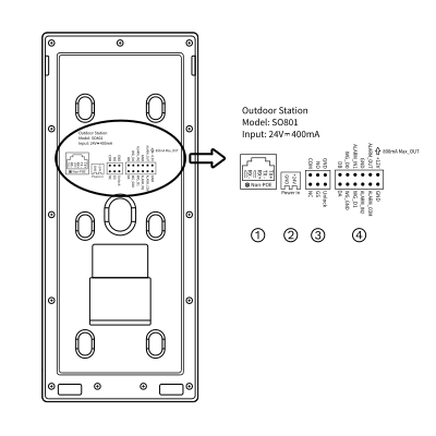
  1. RJ45 Network interface
     
  2. Power input interface DC 24V (independent power supply interface, voltage range DC 18-30V)
     
  3. COM, NO, NC: Common terminal, normally open terminal and normally closed terminal of the unlocking relay. 
    GS: Door state detection input terminal.  
    UNLOCK, GND: Door unlock switch input
     
  4. WG-GND, WG-D0, WG-D1: Wiegand interface. 
    DA, DB: 485 communication interface. 
    ALARM_IN1: Alarm input 1. 
    ALARM_IN2: Alarm input 2. 
    GND: GND. 
    ALARM_OUT: Lock2 interface normally open. 
    ALARM_COM: Lock2 interface common port GND. 
    +12V_OUT: +12V power output

3. What you need

Wired, SIP based. Needs a PIERRE display as the indoor unit (the Smart PIERRE app can also answer calls), a network switch and a DC power supply (see the power input in Product Description).

4. Product specifications

Technical Specifications

Connectivity

Connectivity 10M/100M Ethernet RJ45
PoE Protocol IEEE 802.3af/at 15.4W/30W

Safety

Safety Features Overload protection, Reverse polarity protection, Tamper protection, Disconnection alarm

Environmental

Operating Temperature -4°F ~ +158°F
Operating Temperature (°C) -20 ~ +70
Operating Humidity ≤95% RH, Non Condensing % RH

Features

LED Indicators Yes

Electrical

Power Supply DC 18-30V
Output Voltage 12V DC / 5V DC
Standby Power <150mA (DC24V)
Working Current <400mA (DC 24V)

Hardware

CPU 2 x Cortex-A7 1.2GHz 32K
Operating System Linux
Memory (RAM) 0.512 GB
Memory (ROM) 4 GB

Display

Touch Screen Dimension 8 inch
Touch Screen Resolution 800x1280px pixels

Physical

Panel Material Metal
Product Color Grey
Mounting Type Wall mount
Bolt Hole Distance 114 mm
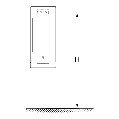
Recommended Installation Height 1.60 m

5. Installation height

Image

Recommended installation height: H = 1.60 m (5.25 ft)
6. Installation Steps

Image

Wall mount

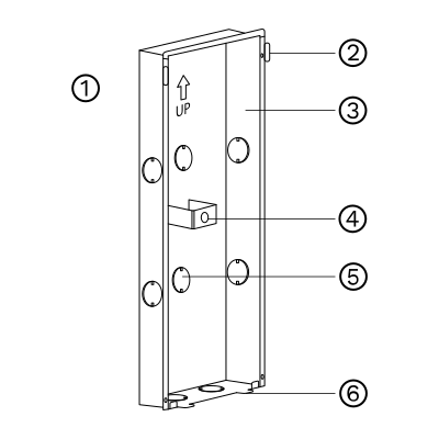
Carefully insert the embedded box into the pre-prepared wall groove, ensuring that the box fits securely and flush with the surface. Route the installation cables through the designated cable opening located at the rear or bottom of the box to allow for proper connectivity during device installation.

Embedded box dimensions (W × H × D):
114 × 292.5 × 38 mm

Ensure that the groove is cut accurately to match these dimensions, providing a snug and stable fit for the embedded box without excessive force or gaps.
  1. Wall
  2. Hook
  3. Embedded box
  4. Magnet
  5. Opening
  6. Anti-removal plate

Image

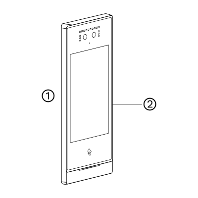
After connecting the cable to the outdoor station, align the positioning slot on the rear side of the device with the corresponding snap mechanism on the embedded box. Once aligned, press the outdoor station firmly onto the embedded box until it securely snaps into place.

Ensure the connection is stable and that the device sits flush against the wall to guarantee proper weather protection and reliable operation.
  1. Wall
  2. Outdoor station

Image

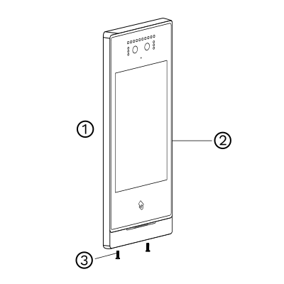
Once the outdoor station is properly snapped into place, fix the unit by tightening the screws located at the bottom of the aluminum panel. This ensures the device is securely fastened to the embedded box and prevents any unintended movement or tampering.

Use appropriate tools and avoid over-tightening to prevent damage to the panel.
  1. Wall
  2. Outdoor station
  3. Screws

7. Wiring Diagrams

Image

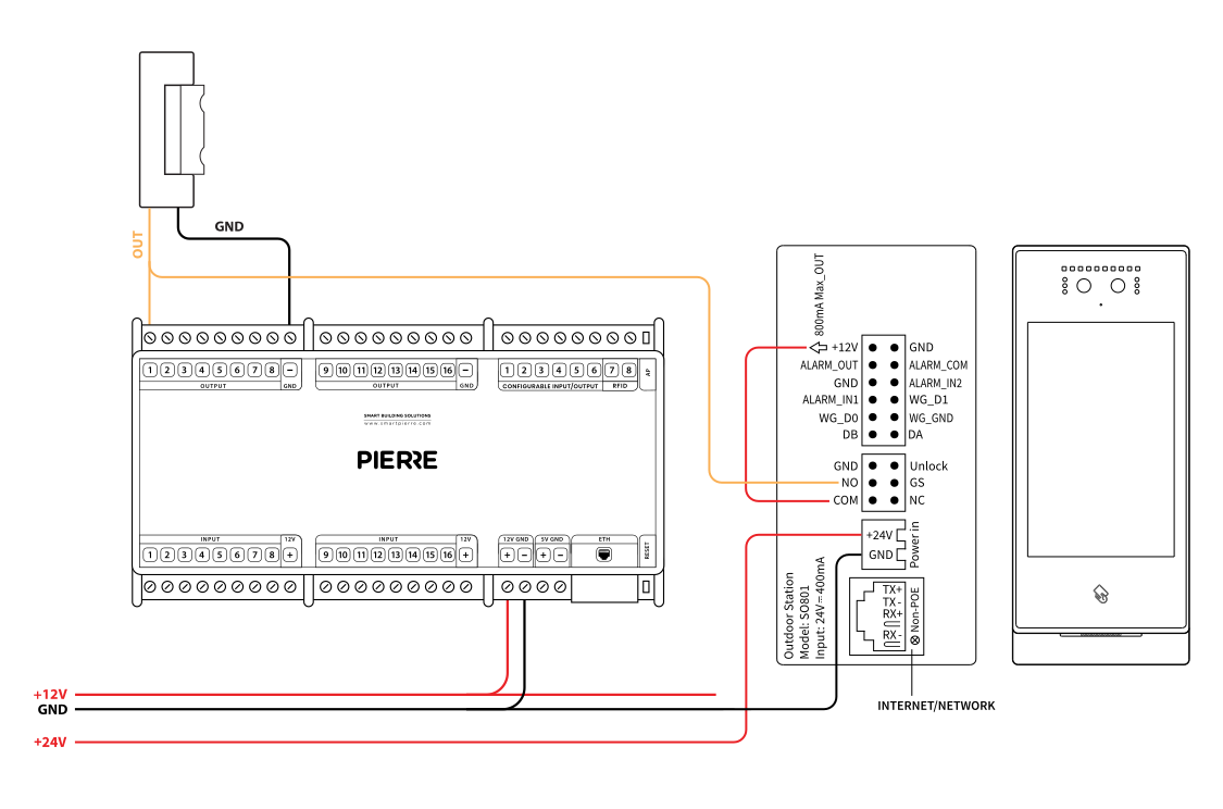
PIERRE Boston Intercom Wiring-hybrid (PIERRE Controller and Intercom)

  • Boston Intercom Relay (NO/COM) → PIERRE Lock Input
    • Triggers the controller to unlock the door.
  • PIERRE Controller → Electric Lock
    • Powers and controls the lock directly.
  • DC power supply for each device (see the power input voltage of the intercom in Product Description and of the PIERRE Controller in its manual).
  • (Optional) LAN for SIP/cloud features.

Note: Ensure correct polarity, relay type (NO/NC), and secure grounding.
Image

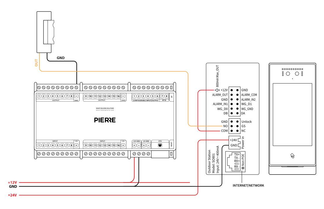
PIERRE Boston Intercom Wiring – Gate/Door opening by Intercom

This diagram shows how the intercom system connects to both a gate and a door lock:

  • LOCK1 → Main Door Lock
    • Controls the building’s primary entrance (electric strike or magnetic lock).
  • LOCK2 → Gate Lock
    • Used to control a secondary entrance such as a vehicle gate or pedestrian gate.
  • Exit Button → Intercom Input
    • Allows unlocking from inside via a push button.
  • Door Sensor Input
    • Detects if the door is open or closed.
  • 12V DC Power Supply
    • Provides power to the intercom and lock control circuits.

Note: Use CAT5e/CAT6 for control lines and ensure proper voltage for locks.
Image

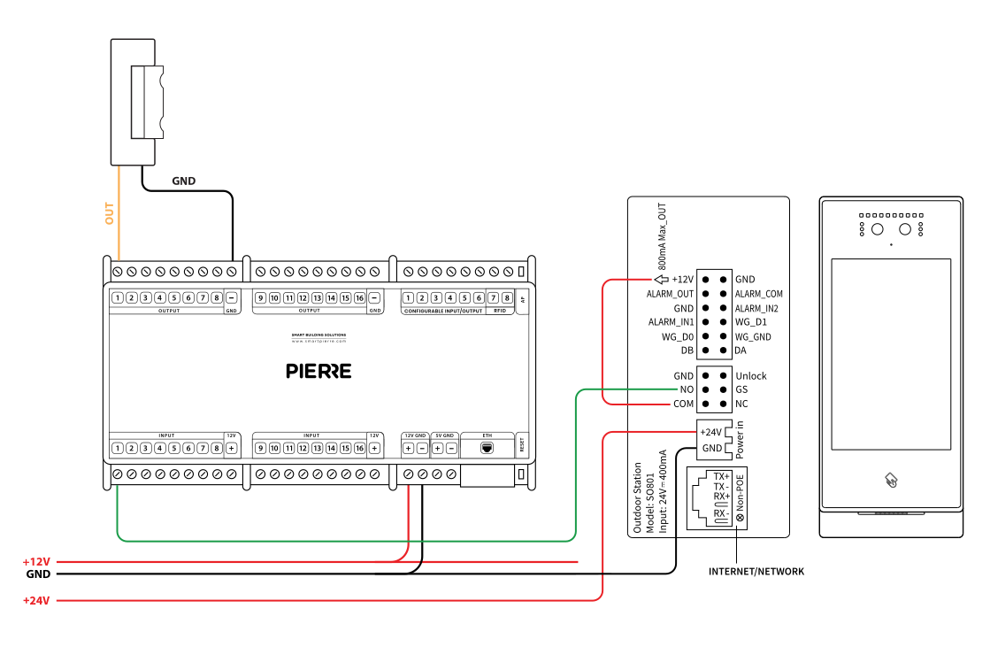
PIERRE Boston Intercom Wiring Gate/Door opening by PIERRE Controller

This setup shows how the intercom is integrated with a gate, a main door, and the PIERRE access controller:

  • Boston Intercom Relay Output → PIERRE Controller Input
    • Sends unlock signal from the intercom to the PIERRE controller.
  • PIERRE Controller → Gate Lock (Lock2)
    • Manages gate access control.
  • PIERRE Controller → Door Lock (Lock1)
    • Manages main door locking.
  • Exit Button → Intercom or PIERRE Controller
    • For manual unlocking from inside.
  • 12V DC Power Supply
    • Powers the intercom, PIERRE controller, and connected locks.

Note: Use proper relay wiring (NO/COM), and confirm all devices share a stable 12V power source. Ensure polarity and grounding are correct.

Run Wires Cross-section Cable type Conductors
From PIERRE to Smart Intercom 1 cat.5 Cat 5e U/UTP 12 V, GND
From Intercom to Network switch 1 - Cat 5e U/UTP -

8. Network Configuration for PIERRE Intercoms

The PIERRE intercoms are SIP-based and work on an offline-first principle: calls are set up over the local network, and remote access is added when an internet connection is available. A dedicated SIP server is not required for local calls.

A network router is a required component of the PIERRE door entry system.

Configure the DHCP server range on the router according to the size of the project.

Example – residential building with 50 apartments:

  • Router IP address: 192.168.1.100
  • Fixed IP addresses of the PIERRE displays (intercom indoor units):
    • Apartment 1: 192.168.1.1
    • Apartment 6: 192.168.1.6
    • Apartment 50: 192.168.1.50
  • DHCP server range on the router: 192.168.1.101 – 192.168.1.254

Every PIERRE display needs a fixed IP address. Assign a fixed IP address outside the DHCP range to every display so that the intercom can always reach it.
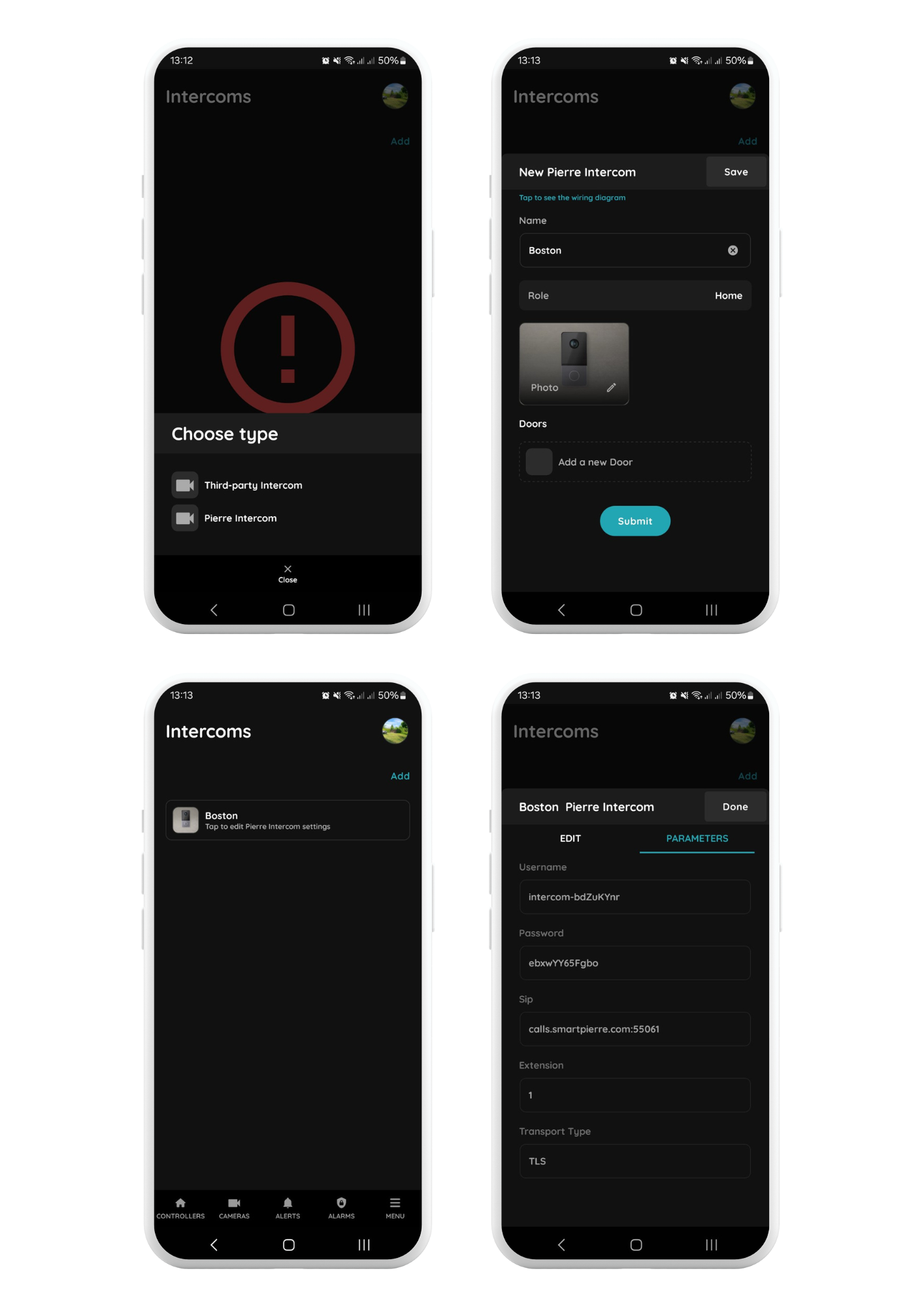
9. Setup in PIERRE Partner Application

Image

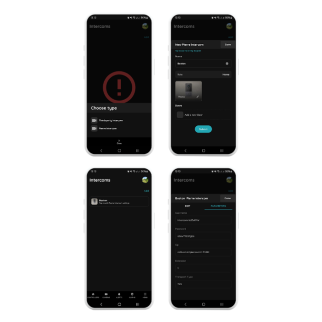
Menu → Intercoms → Add

Select the PIERRE Intercom
Choose the PIERRE Intercom from the list of available devices.

Configure the Intercom Settings

  • Name: Enter a name for the intercom.
  • Role: Select the role for the intercom.
  • Doors: Select the doors that can be unlocked with the intercom.

Save the Configuration
Tap Save. After saving, open the new intercom to view or modify its settings.

Access Parameters
Open the Parameters tab. The following parameters are generated automatically and must be entered in the intercom:

  • Username – as shown in the PIERRE Partner app
  • Password – as shown in the PIERRE Partner app
  • SIP – PIERRE SIP server parameters
  • Extension – 1 (with several intercoms in one system the extension is incremented automatically)
  • Transport Type – TLS

10. Set up the PIERRE Boston intercom

  1. Settings
    1. Click on the Settings icon.
    2. The default password is 801801.
      Important: Always change this password at the end of the setup process and document it securely.
  2. Call Settings
    1. Call Settings and then navigate to the SIP Account Settings section.
  3. SIP Account Configuration
    1. Username: this is the EXTENSION from PIERRE Partner application.
    2. Local SIP Account - This is automatically generated by the system. No changes are required.
      Format: sip:extension@ip-address:port

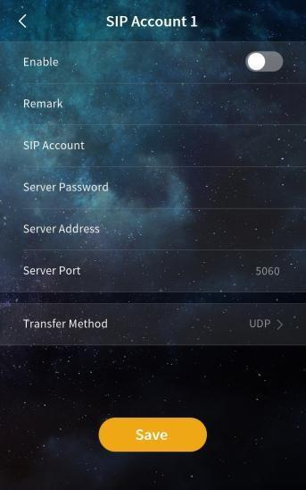
      SIP Account 1
      1. Username: Enter the Username generated in the PIERRE  Partner application.
      2. Server Password: Use the Password generated in the PIERRE Partner application.
      3. Transfer Method: Set to TLS (Transport Layer Security) to ensure compatibility with providers that use double NAT (CGNAT).
  4. Save and Verify Connection
    1. Save the settings and exit the menu.
    2. Re-enter the SIP Account Settings to confirm the status.
      1. The status should now display Connected.

11. Configuring the Call Recipients on the Door Intercom

To enable call forwarding from the door intercom to a designated recipient, follow the steps below to add SIP contacts.

  • Step 1: Access Intercom Settings
    • Navigate to the Settings menu on the intercom device.
    • When prompted, enter the default access password: 801801.
  • Step 2: Open Call Settings
    • Within the settings menu, select Call Settings, then proceed to Contact List Management.
    • Tap Add to and select Add Contacts to begin adding a new recipient.
  • Step 3: Add a Contact
    • Remark: Enter a clear and descriptive name to identify the contact (e.g., Apartment 1 – John Doe).
    • SIP Account: Input the SIP address in the following format:
    • sip:1@192.168.1.1:5060
    • (Replace with the actual local IP address of the PIERRE indoor monitor/display.)
    • Tap SAVE to store the contact.
  • Step 4: Verify Functionality
    • After saving, perform a test call to confirm successful registration and two-way communication with the configured SIP contact.

12. Assigning Fixed IP Addresses to Displays

Step 1: Open the network settings

  • On the display, pull down the status bar from the top of the screen.
  • Wi-Fi is optional and is not needed for the intercom. Use Ethernet for the intercom network.

Step 2: Set Ethernet to a static address

  • Select the Ethernet (primary) network.
  • Open IP Settings and select Static.

Step 3: Assign the fixed IP address

  • IP address: a fixed address outside the DHCP range of the router.
  • Gateway: the IP address of the router.
  • Subnet mask: as used on the network (usually 255.255.255.0).
  • DNS: as required by the network.

Step 4: Router

  • The router distributes IP addresses (DHCP) to all other devices.
  • The display addresses must stay outside the DHCP range.

13. Example configuration for smaller projects (up to 45 apartments)

Router DHCP server start address: set the DHCP server to distribute addresses from, for example, 192.168.1.101.

Static IP range for displays: assign static addresses below the DHCP range, for example:

  • Display for Apartment 1: 192.168.1.1
  • Display for Apartment 6: 192.168.1.6
  • Display for Apartment 45: 192.168.1.45

This avoids IP conflicts between the displays and the DHCP clients.
14. Basic Functions

  • When the device is powered on for the first time, the user needs to select the language and set up the network.
  • The functions below the main interface can be turned on or off in the system settings.

15. Call Management Center

Image

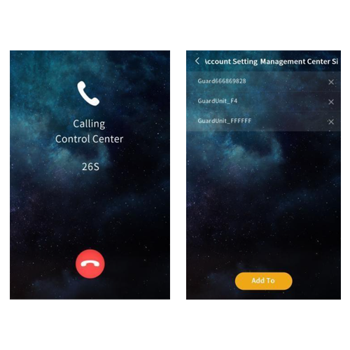
Tap to call the SIP account of the management center, and the outdoor station has ring back tones. If there is no answer from the management center within 30s, the call will be ended automatically. 

Note: Support calling multiple management center SIP accounts at the same time, set in "Call Settings-Management Center SIP Account".

16. Face recognition & QR code Unlocking

Tap icon to scan the face or the QR code for unlocking. Once the face and QR code is recognized as correct, the door will be unlocked. 

Note:
  • When the user whose face has been registered approaches and faces the camera of the outdoor station, the device automatically enters face recognition unlock mode.
  • The QR code for unlocking is generated by the mobile APP. In the mode of not using the server, there is no QR code unlock function.

17. Public password / unlock code unlocking

Image

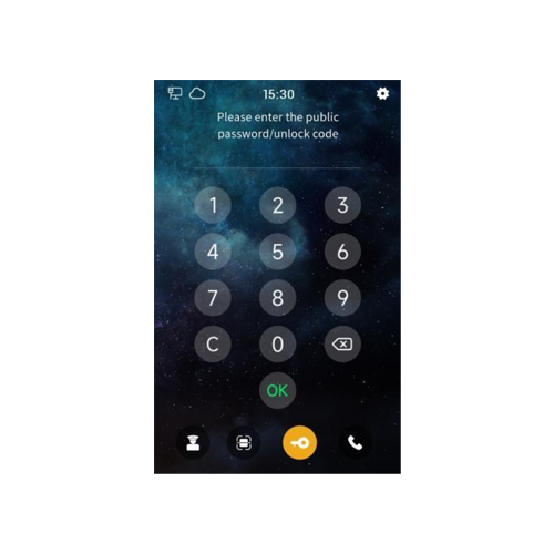
Tap icon to enter the public password/ unlock code to unlock. Once the password/code is recognized as correct, the door will be unlocked. 

Note: 
  • The default public password is 666666, which can be modified in "Access Control Settings-Unlock Settings".
  • The unlock code is generated by the mobile APP. In the mode of not using the server, there is no unlock code function.
  • Both public password unlocking and unlock code unlocking can be turned on or off in the system settings.

18. Name List Call & Dial Call

Image

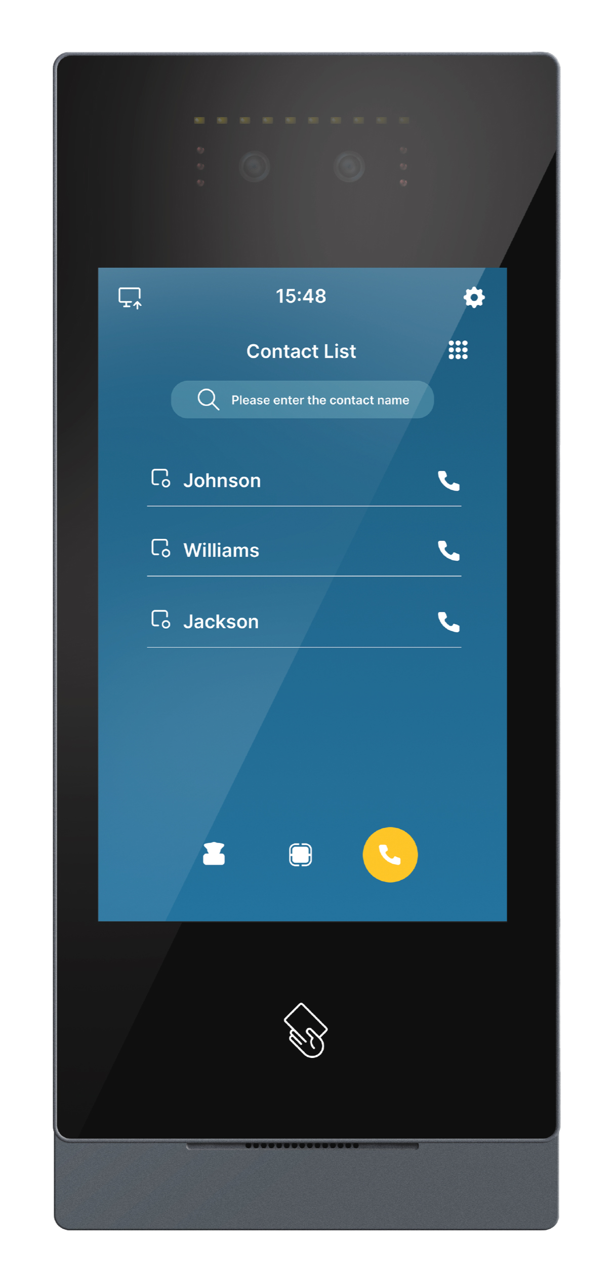
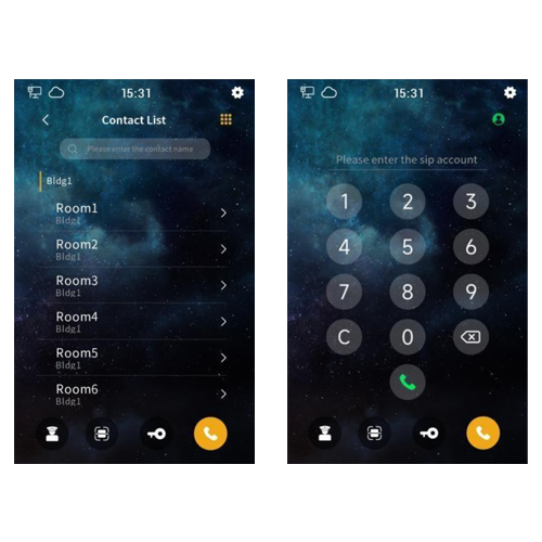
Tap icon to call the corresponding resident through the name list. Click the icon in the upper right corner to switch from the name list call interface to the dial call interface. You can call the corresponding resident by entering the SIP account user name corresponding to the device, for example, the SIP account "sip: 000100011@192.168.150.100:8060", enter "000100011" to call. 

Note: 

  • The management center or the indoor station can control the unlocking of the outdoor station when they are in communication.
  • Both name list calling and dial calling can be turned on or off in the system settings.

19. System Setting

Tap icon in the upper right corner to enter the system setting interface by inputing the correct engineering password (the default is 801801, which can be modified).
20. Sound Setting

Image
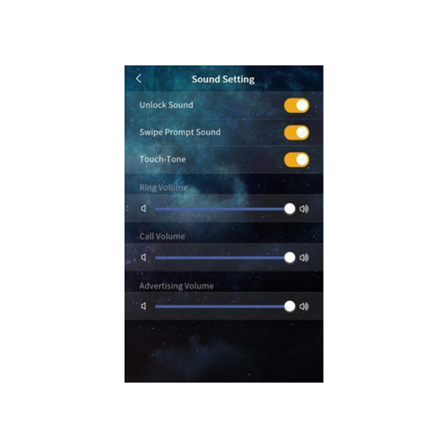
  1. Unlock prompt sound: After it’s enabled, the device will have sound feedback when the door is unlocked.
  2. Card swiping prompt sound: After it’s enabled, the device will have sound feedback when the user swipes the card.
  3. Touch-Tone: After it’s enabled, the device will have sound feedback when user clicks the screen.
  4. Ringtone volume: The volume of the ringtone can be adjusted.
  5. Call volume: The volume of the call can be adjusted.
  6. Advertisement volume: The volume of the advertisement can be adjusted.

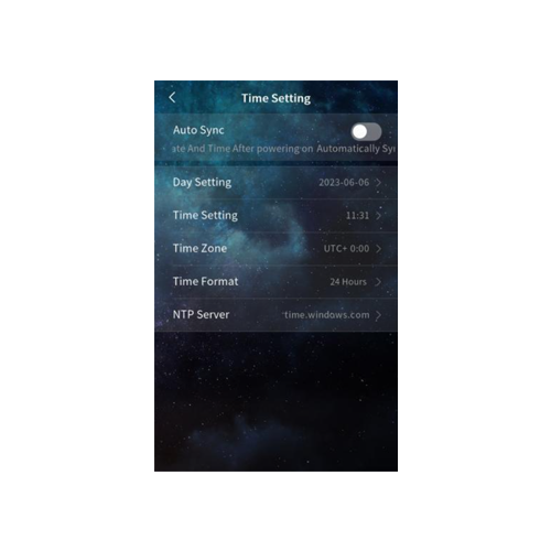
21. Time setting

Image
  1. Automatic synchronization and manual setting: If automatic synchronization is enabled, the device will automatically synchronize the network date and time. If automatic synchronization is disabled, you can manually set the year, month, day, hour and minutes.
  2. Time zone: Select the corresponding time zone according to the country you are in. After the automatic time synchronization is enabled, the device will convert the local time according to the set NTP server and time zone.
  3. Time format: 24-hour or 12-hour format can be selected.
  4. NTP server: Enable the device to obtain accurate clock time from the set NTP server address.

22. Language setting

Image

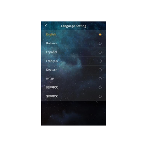
Options: English, Italiano, Español, Français, Deutsch, עברית, 简体中文, 繁體中文.
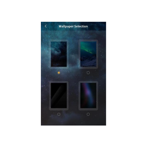
23. Wallpaper selection

Image

Changeable wallpaper. Custom wallpaper configuration can be done through the PC upgrade tool.
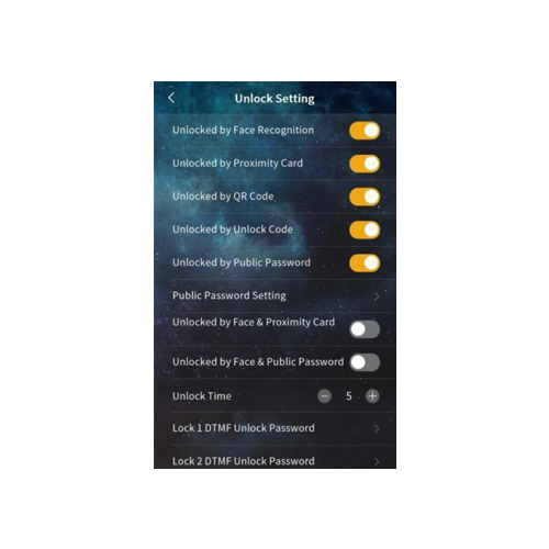
24. Unlock Setting

Image
  1. Face recognition unlocking: After this option is selected, users with registered faces can unlock the door through the device's camera.
  2. RFID card unlocking: After this option is selected, users can unlock the door by putting the registered RFID card close to the card swiping area of the outdoor station.
  3. QR code unlocking: After this option is selected, users can unlock the door by scanning the QR code generated by the mobile APP through the device at the "main page - face recognition & QR code unlocking". 
    Note: When the server mode is not used, there is no QR code unlock function.
  4. Unlock code unlocking: After this option is selected, users can unlock the door by entering the unlock code at the "Main Page-Public Password/Unlock Code". 
    Note: When the server mode is not used, there is no unlock code function.
  5. Public password unlock: After this option is selected, users can unlock the door by entering the public password at the "main page - public password/unlock code".
  6. Public password setting: The public password can be modified.
  7. Face recognition + RFID card combination unlock: After this option is selected, the device will simultaneously enable face recognition and IC card unlock function. Door will be unlocked only with correct face recognition and RFID card.
  8. Face recognition + public password combination unlock: After this option is selected, the device will simultaneously enable face recognition and public password unlock function. Door will be unlocked only with correct face recognition and public password.
  9. Unlocking time: The duration of door unlocking can be modified, and the door will be automatically closed after timeout. The optional range is 1-60s.
  10. Lock 1/Lock 2 DTMF unlock password: Set the DTMF unlock password for Lock 1/Lock 2, the default for Lock 1 is 666666, and the default for Lock 2 is 888888. Only when the DTMF password of the outdoor station and the indoor unit are set consistently, the outdoor station can unlock lock 1/lock 2.

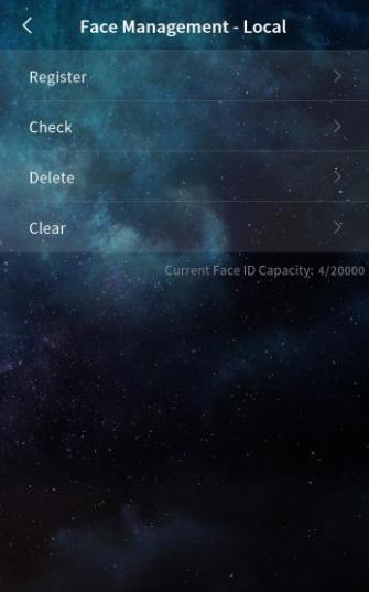
25. Face management

Image

You can register, view, delete, or clear face data directly on the outdoor station. When using either the default server mode or a custom server mode, the face data is automatically synchronized with the central platform. The outdoor station supports storage of up to 20,000 face entries.
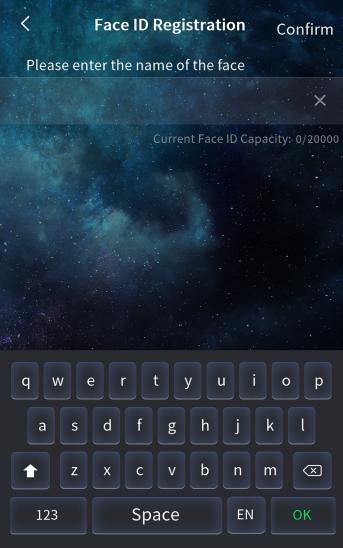
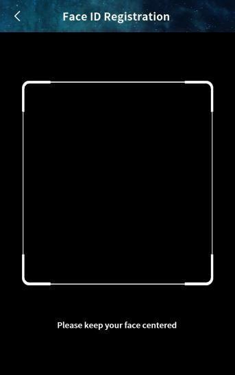
  1. Register
    1. To register a face, go to the face registration interface. First, enter the person's name, then click Confirm. Position the face in front of the camera to complete the registration. When the outdoor station displays the message "Registered successfully", the face has been successfully added.

Image
  1. Check
    1. To view face information, enter the person's name in the search box. The corresponding face data will be displayed.
  2. Delete
    1. To delete a face, enter the person's name in the search box and remove the corresponding face data.
  3. Clear
    1. This option allows you to clear all face data stored on the device.
Image
  1. Face Photo Saving
    1. When this option is turned off, the outdoor station will stop saving face photos and will delete any previously stored photos.
    2. When the option is turned on, the device will save face photos, which can then be viewed directly on the device.

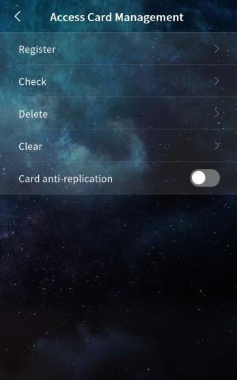
26. Access Card Management

Image

Managing Access Card Information on the Outdoor Station

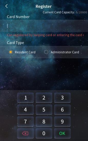
You can register, view, delete, or clear access card information directly on the outdoor station. In both default server mode and custom server mode, card data is automatically synchronized with the central platform. The outdoor station can store up to 20,000 access cards.
Image
  1. Register
    1. To register a card, go to the card registration interface. First, swipe the card or manually enter the card number. Then, select the card type (Resident Card or Administrator Card) and click OK. When the outdoor station displays "Registered successfully," the card has been added successfully.
Image
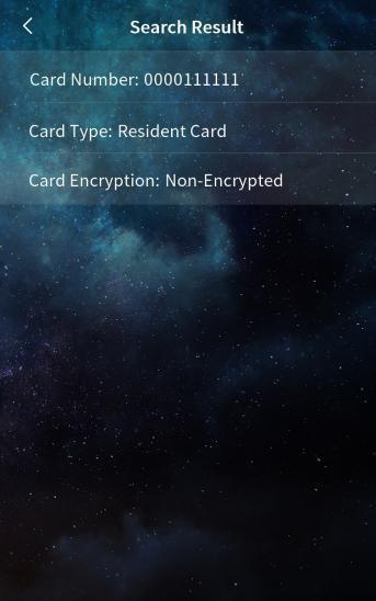
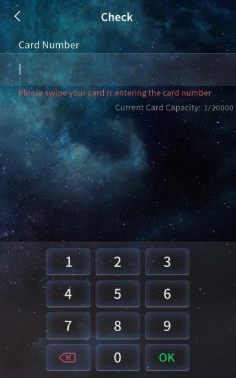
  1. Check
    1. To view access card information, swipe the card or enter the card number in the search box. The corresponding card details will be displayed.
  2. Delete
    1. To delete an access card, swipe the card or enter the card number in the search box. Then, delete the corresponding card data.
  3. Clear
    1. This option allows you to erase all Resident Card and Administrator Card data stored on the device.
Image
  1. Card Replication Prevention
    1. When this option is enabled, registered cards are encrypted, making them non-copyable and protected against duplication.

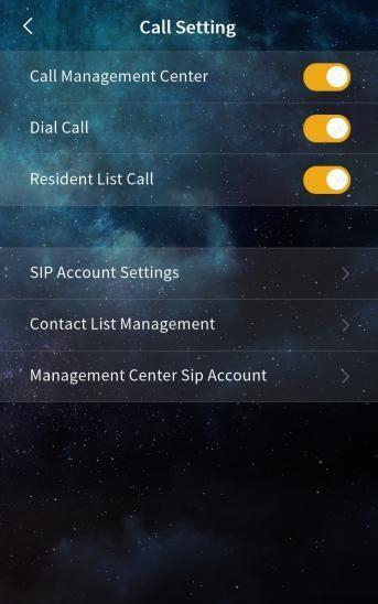
27. Call Setting

Image
  1. Call Management Center
    1. When this function is enabled, a button appears on the main interface allowing users to directly call the management center with a single tap.
  2. Dial Call
    1. When enabled, this feature allows users to enter a SIP account on the main screen to call a specific household.
  3. Contact List Call
    1. When this option is turned on, a contact list becomes available on the main interface. Users can select a contact from the list to call the corresponding household.
Image
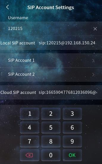
  1. SIP Account Settings
    1. Username: Enter a username to configure the local SIP account for making dial-up calls. Note: The username must be unique within the same network; duplicate accounts are not allowed.
    2. Local SIP Account: This shows the full local SIP account, which is generated based on the entered username and the device’s IP address. It is used to call other accounts within the same network.
Image

SIP Account 1 and 2

You can manually configure SIP account settings and choose whether to enable each account. The following information must be entered:

  • Username
  • Server password
  • Server address
  • Server port

Additionally, select the desired transmission mode: UDP or TLS.

Optionally, you can configure the SIP account using address book information by setting the device name.

Cloud Intercom SIP Account

This displays the SIP account assigned to the device by the cloud server when the device is connected to the cloud. This account is used for cloud-based intercom functionality.
Image
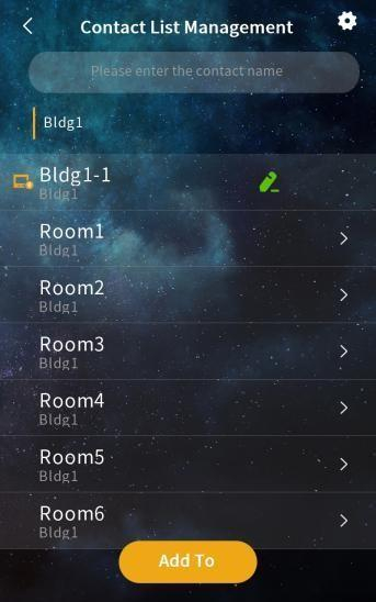
  1. Contact List Management

This feature displays information about all current contacts. Contacts may include:

  • Devices automatically discovered when automatic configuration is enabled
  • Devices imported from the address book
  • Devices manually added by the user

Search

You can perform a fuzzy search to quickly find contacts in the list based on partial information.

Settings

Choose whether to display profile pictures for contacts.

Configure the display range of the contact list:

  • When disabled, all contacts are shown.
  • When enabled, you can filter to show only specific groups or selected contacts.

Add

You can add contacts manually by entering the following details:

  • Remarks (display name)
  • SIP account
  • Owning group

You can also create new groups by setting a group name (remark), enabling group calling, and assigning an owning group.

Edit

Allows you to modify the information of existing contacts.

Delete

Deletes contact entries.

Note:
  • Devices discovered via automatic configuration cannot be deleted while they are online.
  • Devices imported from the address book cannot be deleted.

Image
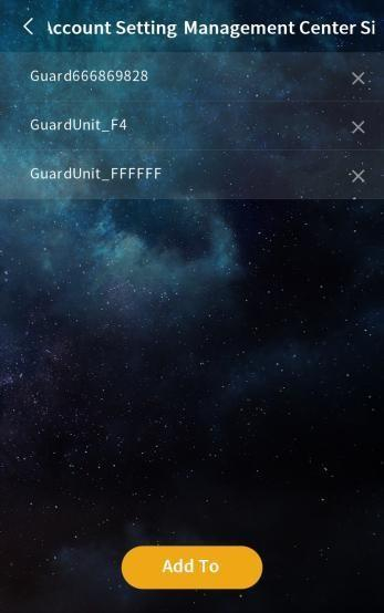
  1. Account Setting – Management Center SIP

This section displays the SIP accounts assigned to management personnel. When a user taps Call Manager, all SIP accounts listed here are called simultaneously.

Add
Click Add To, then select devices to include in the manager list. You can add up to 10 SIP accounts to the management SIP account list.
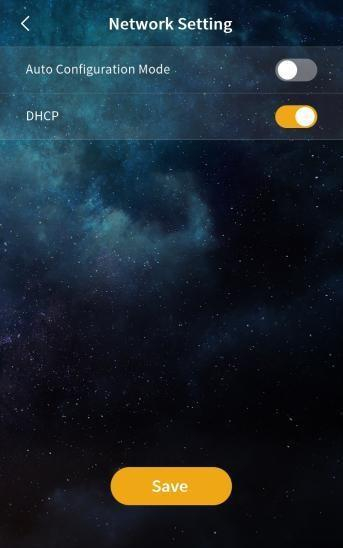
28. Network Setting

Image

Automatic Configuration Mode

When this option is enabled, the device can automatically discover other intercom devices of the same series on the same network segment.
Image

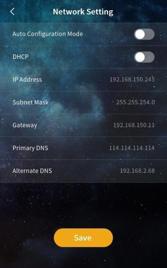
DHCP

When DHCP is disabled, network settings must be configured manually. You will need to enter the following information:
  • IP address
  • Subnet mask
  • Gateway
  • DNS server

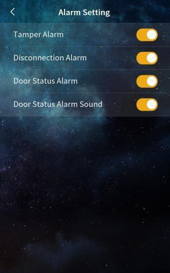
29. Alarm Setting

Image

Tamper Alarm

When enabled, the device will sound an alarm if it is physically tampered with or dismantled by force.

Disconnection Alarm

When this option is turned on, the device will emit an alarm tone and display a disconnection icon in the status bar if it loses network connection.

Door Status Alarm and Alarm Tone

When both the Door Status Alarm and Alarm Tone are enabled, the device will trigger an audible alarm if the door remains open for more than 120 seconds.
30. Engineering Setting

Image

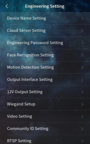
The Engineering Setting menu provides advanced configuration options for installers and system administrators.

This section allows you to fine-tune device behavior, connectivity, and integration with external systems.

Available options:
  • Device Name Setting: Set or modify the name of the device for easier identification on the network.
  • Cloud Server Setting: Configure connection details for the cloud platform.
  • Engineering Password Setting: Set or change the password required to access engineering-level settings.
  • Face Recognition Setting: Adjust parameters related to face recognition functionality.
  • Motion Detection Setting: Enable and configure motion detection features.
  • Output Interface Setting: Set the behavior of output interfaces for access control or alarms.
  • 12V Output Setting: Configure the 12V power output timing and usage.
  • Wiegand Setup: Set Wiegand input/output parameters for integration with access control systems.
  • Video Setting: Configure video-related options such as resolution, brightness, and stream settings.
  • Community ID Setting: Assign or change the Community ID used in multi-device environments.
  • RTSP Setting: Enable and set up RTSP streaming for video surveillance integration.

Image

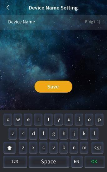
Device Name Setting

You can modify the device name in this menu. If you need to use SIP account information from the address book, set the device name to match the corresponding name listed in the address book.
After setting the name, the device will prompt you to confirm whether to use the associated SIP account information from the address book.
Image

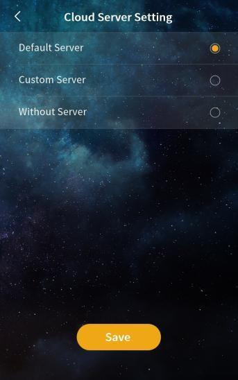
Cloud Server Settings

This setting allows you to configure how the device interacts with a server for storing and synchronizing face and access card data. You can choose between three modes: Default Server, Custom Server, or No Server.

Default Server / Custom Server Mode

  • In these modes, the device uploads locally registered face and access card data to the server.
  • It also synchronizes data from the server to ensure consistency across devices.
  • When switching from a server mode to no server, you can choose whether to retain or clear the server data:
    • Retain: Data previously sent from the server remains on the device.
    • Do not retain: The device clears all server-synced data.

No Server Mode

  • This is also known as single-device mode. All face and access card data is stored locally on the device only.
  • When switching to a server mode (default or custom), you can choose whether to upload the local data:
    • Upload: Local data is uploaded to the server and merged with server data.
    • Do not upload: Local data is cleared, and only the data from the server is synchronized to the device.

Image

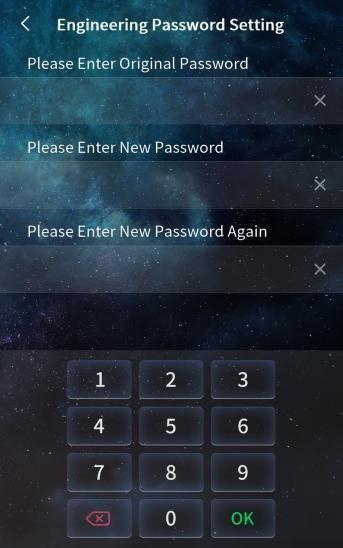
Engineering Password Setting

This option allows you to change the engineering (project) password. The password must be exactly 6 digits long and is required to access advanced configuration settings.
Image

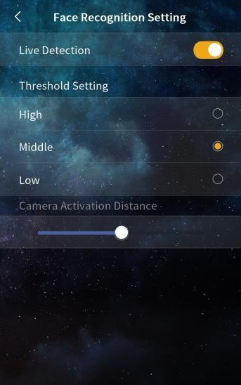
Face Recognition Settings

Live Detection Switch

When enabled, the device performs live detection to ensure that only real, live faces can unlock the system. Faces that are not detected as "live" (e.g., photos or videos) will be denied access.

Threshold

Sets the sensitivity level for face recognition:

  • High: Requires a high degree of facial similarity; users must be very close to how they appeared during registration.
  • Medium: Balanced matching sensitivity.
  • Low: More lenient matching, suitable for more flexible use cases.

Camera Wake-Up Distance Adjustment

Allows users to set the distance at which the camera wakes from screensaver mode to start face recognition.

Adjustable range: 0.3 to 2 meters

When set to the maximum (2 meters), the device will automatically activate face recognition when a face is detected within 2 meters during screensaver mode.
Image

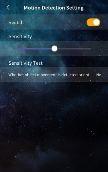
Motion Detection Settings

Switch

When enabled, the device activates motion detection. If a moving object is detected near the door station, the screen will light up and display the main interface.

Sensitivity Adjustment

This setting allows you to adjust how sensitive the motion detection is:

  • Low Sensitivity: The object must be closer to the device to trigger detection.
  • High Sensitivity: Detection will be triggered by motion at a greater distance.

Sensitivity Test

This feature helps verify whether motion is detected within the current detection range.

  • If motion is detected, the result displays "Yes".
  • If no motion is detected, it displays "None".

Use this test to fine-tune sensitivity settings and ensure optimal performance.
Image

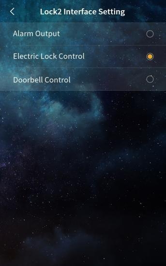
Lock2 Interface Functions

The Lock2 interface supports multiple configurable functions. You can select one of the following options based on your application needs:
  • Alarm Output: Triggers an external alarm device.
  • Electronic Lock Control: Controls the operation of a secondary electronic lock.
  • Doorbell Control: Activates a connected doorbell device.

Image

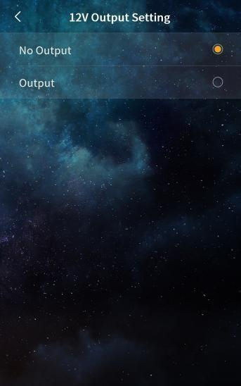
12V Output Setting

This setting allows you to enable or disable the 12V power output.

Note: The Lock2 interface functions (such as alarm output, electronic lock control, or doorbell control) will only operate when 12V output is enabled.
Image

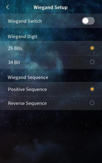
Wiegand Setup

This section allows you to configure the Wiegand interface settings for integration with external access control systems. The following options are available:
  • Switch: Enable or disable the Wiegand function.
  • Bit Selection: Choose the data format—either 26-bit or 34-bit.
  • Sequence Selection: Set the data transmission order to either Normal (positive) or Reversed.

Image

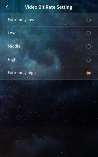
Video Bit Rate Setting

This setting allows you to configure the video bit rate used during calls and monitoring. Adjusting the bit rate can help balance video quality and network performance based on your environment and bandwidth availability.
Image

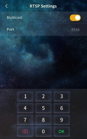
RTSP Setting

Multicast

This option is enabled by default. When enabled, only one indoor unit can monitor the door station at a time.

Note: If you disable this option, multiple indoor units can monitor the door station simultaneously. However, performance may be affected by network conditions such as bandwidth limitations.

Port

Specifies the RTSP streaming port.
  • Default value: 8554
  • Range: 1–65535
    Important: The port setting must match between the door unit and the indoor unit. If the ports are not consistent, the indoor unit will not be able to receive the video stream from the door unit.

Image

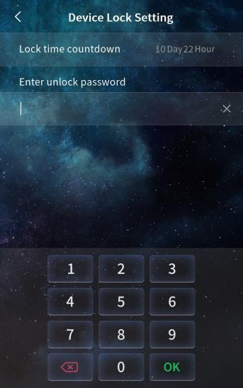
Device Lock Setting

This setting allows you to configure the lock time and set an unlock password to protect the device from unauthorized access.

Note:

If the unlock password is forgotten, the device cannot be unlocked through standard means and must be returned to the factory for reset.
31. About

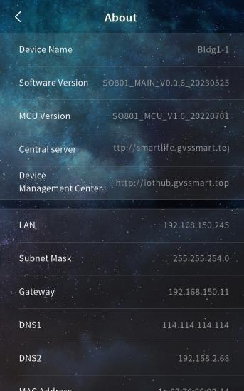
Image

Device Information

This section displays key information about the device, including:
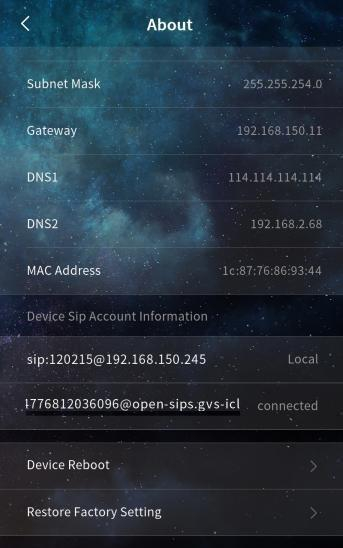
  • Device Name
  • Software Version
  • MCU Version
  • Central Server
  • Device Manager
  • LAN IP Address
  • Subnet Mask
  • Gateway
  • DNS Server

Image
  • MAC Address
  • SIP Account Information

Use this information for system diagnostics, network configuration, and support purposes.

32. Roles and access for the intercom

Role setup for PIERRE intercoms for residential building

The PIERRE intercom must be added to the Common Controller using a separate role.

Each apartment must have access to the intercom and the corresponding door for remote unlocking. The intercom and the associated door must be assigned to a dedicated role named Intercom and removed from the Default role.

The Intercom role must then be assigned to the PIERRE indoor displays (intercom indoor units) and to the users who should be able to receive and answer intercom calls.
Image

Role and door assignment for the intercom

33. FAQ

Q1: Will the intercom work without internet?

Yes. The intercom works locally without internet access. Calls still ring on the PIERRE display, but you cannot receive intercom calls remotely from outside the local network.

Q2: Does the intercom support PoE power supply?

Depending on the model, the intercom can be powered over Ethernet (PoE). Check the product specifications of your model.

Q3: Is an indoor intercom unit required?

No. PIERRE displays work as the indoor intercom unit, so a separate indoor unit is not needed. The Smart PIERRE app on a smartphone can also answer intercom calls.

Q4: Will the intercom ring on my phone if there is no internet?

No. Without internet the intercom does not ring on the phone, but it still rings on the PIERRE display.