User Manual
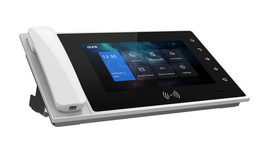
The Receptionist Device
SKU: P-INT-RECEPTIONIST
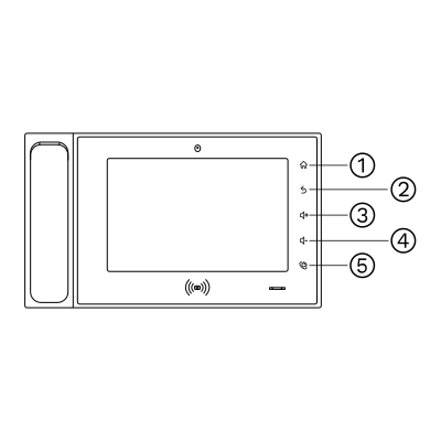
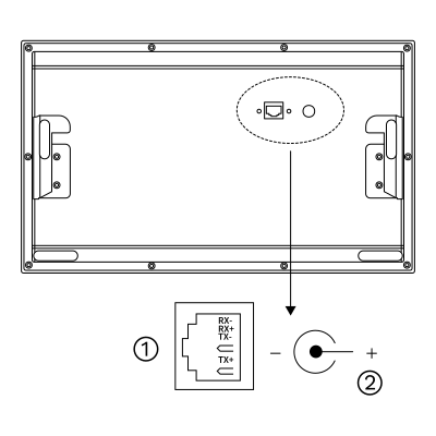
Connects the device to the network switch (Ethernet). It carries the SIP calls to the outdoor intercoms and the PIERRE displays and is used for configuration.
Pin labels: RX-, RX+ (receive), TX-, TX+ (transmit).
DC power input socket.
Power supply: 24 V DC (check the rating label on the device).
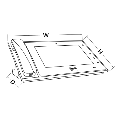
W: 35.5 cm
H: 20.9 cm
D: 10.5 cm
Wired, SIP based management-center (guard) unit for a PIERRE intercom system. Needs at least one outdoor intercom, a network switch and a DC power supply (see the power input in Product Description).
| Run | Wires | Cross-section | Cable type | Conductors |
|---|---|---|---|---|
| From Receptionist to Network switch | 1 | - | Cat 5e U/UTP | - |
The PIERRE Intercoms are SIP-based and operate on an offline-first principle. This means that communication is established over the local network whenever possible. If an internet connection is available, remote communication through the Smart PIERRE app is also supported. As the system is SIP-based, local communication does not depend on a cloud connection.
A network router is a fundamental component of the PIERRE door entry system. The modem/router provided by the internet service provider is suitable for this purpose.
The router must be configured with an appropriate DHCP server IP range, depending on the size of the project.
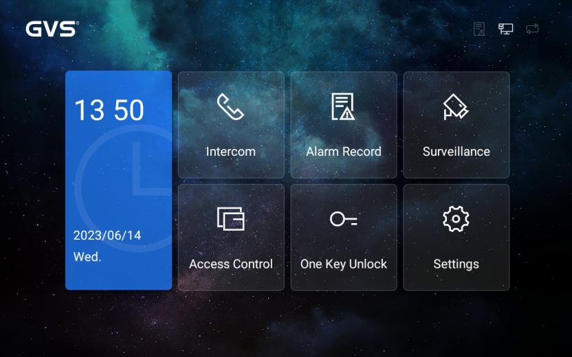

Intercom
Click the icon to view contacts, call history, dial to call and set up contacts.

Alarm Record
Click the icon to check all alarm records.

Surveillance
Click the icon to select devices to monitor in the monitoring list, view monitoring logs and make monitoring settings.

Access Control
Click the icon to register, delete, delete all, search and other operations for the user card.

One Key Unlock
Click the icon to unlock all locks with access control in case of emergency, such as fire, for a duration of 1 hour.
Settings
Click the icon to access the settings interface.
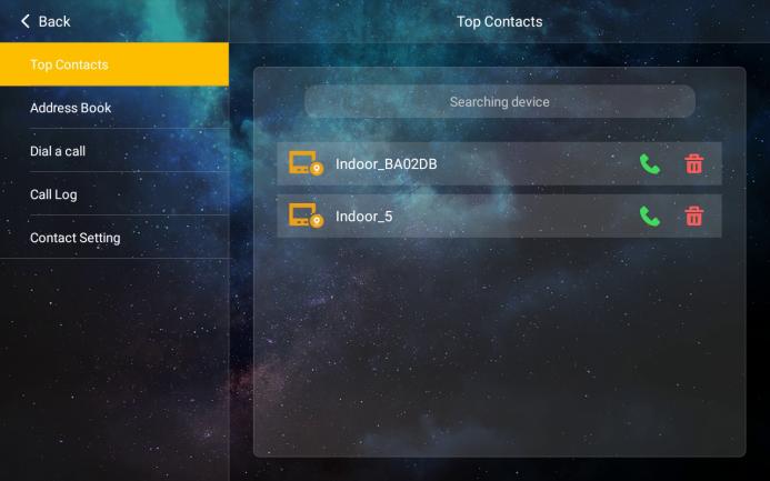
Click on the intercom button and select the type of device to call.

In the contacts, tap the star icon to add the contact to your frequently used contacts for a quick call.
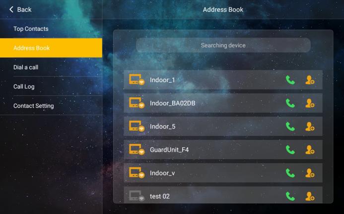
The Address Book shows network devices found with auto-configuration switched on, devices imported from the address book and devices added manually.

Indicates the online devices on the same network discovered by the device.

Indicates a device on the same network that has been discovered but is currently offline.

Indicates a device imported from the address book or added manually on this device.

Click the icon to add the current contact to frequent contacts.
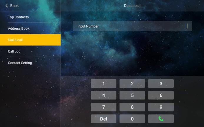
Enter the user name of the SIP account corresponding to the device to call through to the device. For example, if the SIP account is "sip: 000100011@192.168.150.100:8060" ,enter "000100011" to call the device.
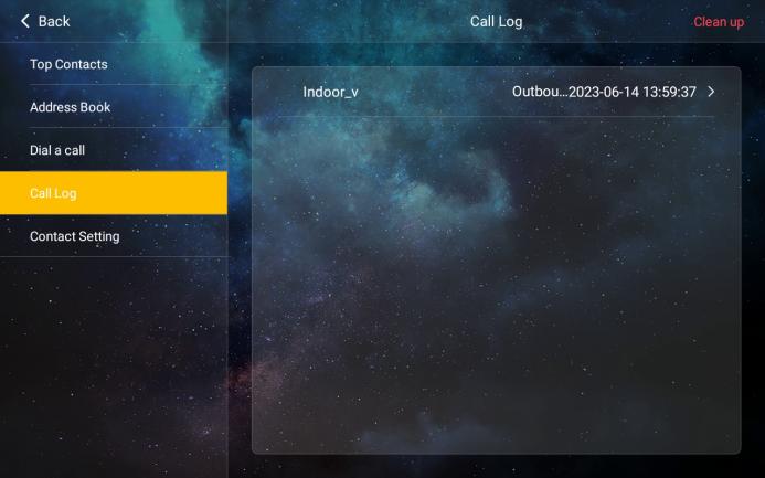
Calls from other devices to this device are listed and unread calls are indicated by a red dot. Call records for which a photo has been captured have a photo icon.
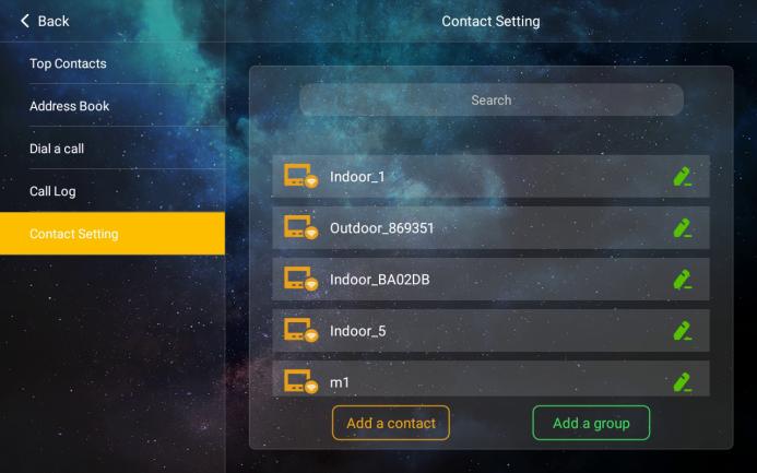
Contacts or groups in the address book can be edited and added.
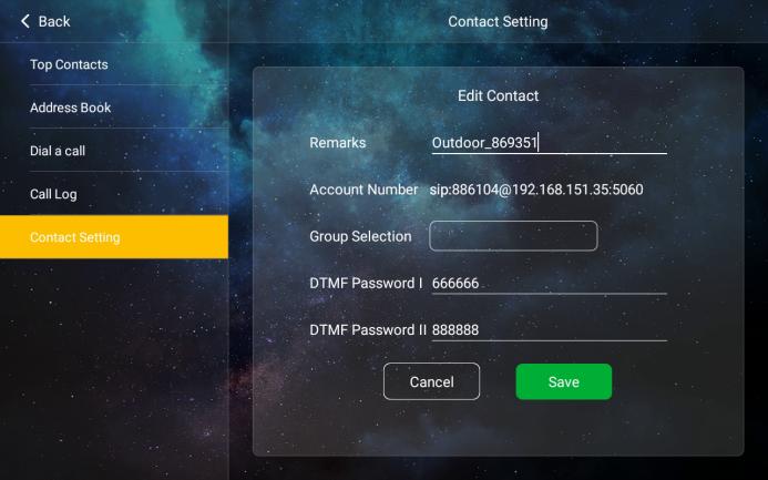
For contacts found by auto discovery or imported from the address book, only the note and the DTMF password can be edited.
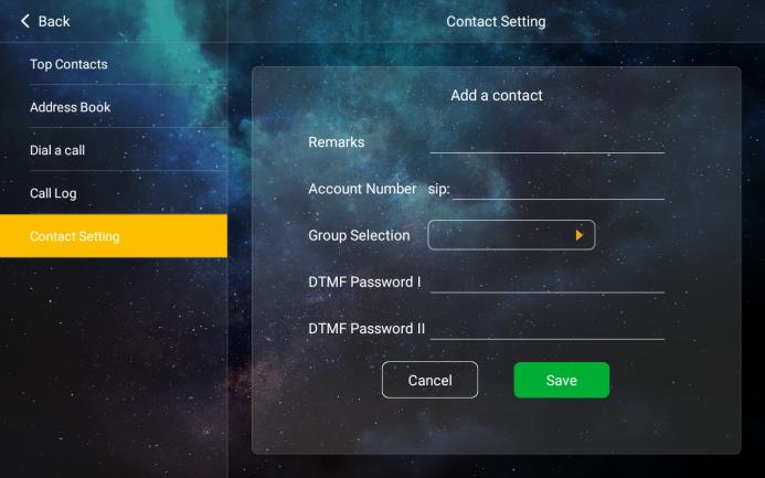
To add a new contact you need to enter the contact notes, SIP account number, select the group the contact belongs to. (If the device has an access control function, you will also need to enter the DTMF unlock code for the device).
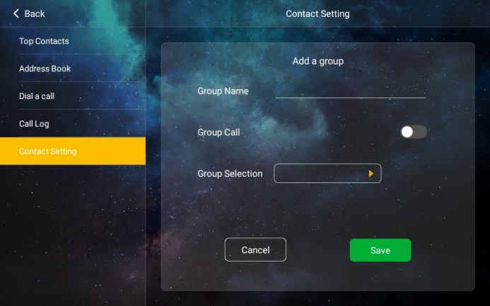
To add a group you need to enter the group name and select the parent group (if none is selected, a top-level group is created).
Only manually added devices and groups, as well as devices found in auto-configuration mode (offline state) can be deleted.
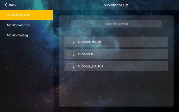
All online devices in the list can be monitored.
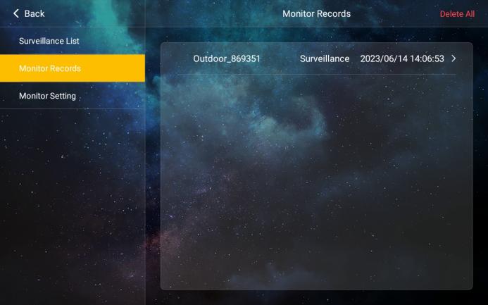
A surveillance record is created by capturing a photo in the surveillance.

Monitor settings to view all monitored URLs.
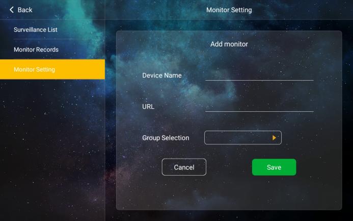
Add monitor: just enter the device name, URL address and select the group it belongs to.
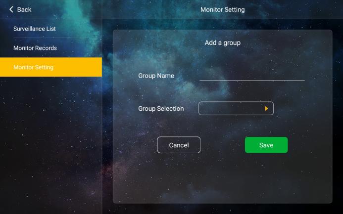
Adding a group: enter a group name and select the parent group to create a group.
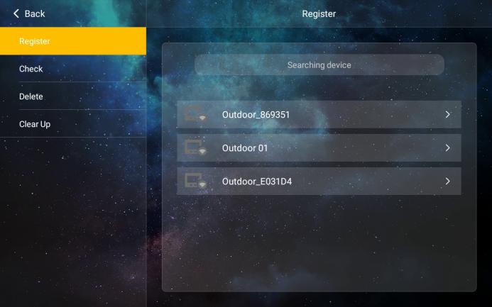
Select the required operations on the left: register, check, delete, and clear up, and select the device to be operated on the right.
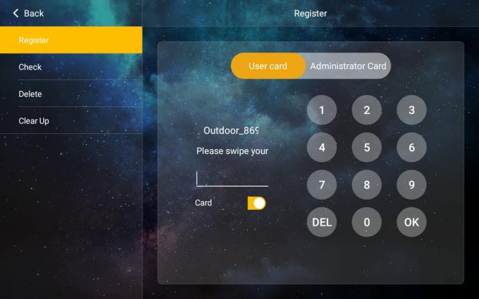
Input card number or swipe card to register, and switch on the Card button to enable the anti-copy function; the card data is then encrypted and cannot be copied.
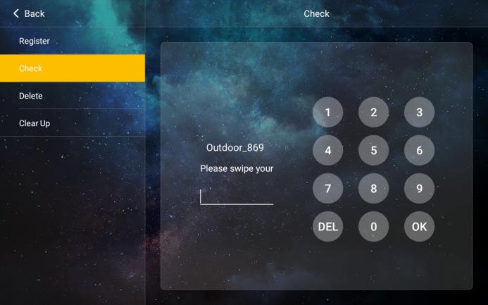
Input card number or swipe card to check if card is registered.
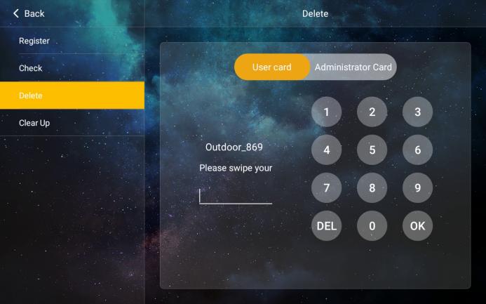
Input card number or swipe card to delete the card.
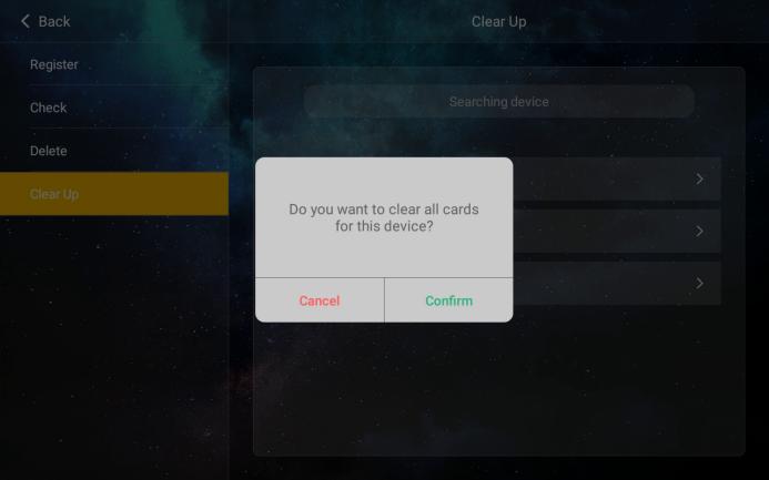
Select device to clear up the data of registered cards.
Users can unlock all locks with access control in case of emergency, such as fire, for a duration of 1 hour.
Note: This function requires entering the user password.
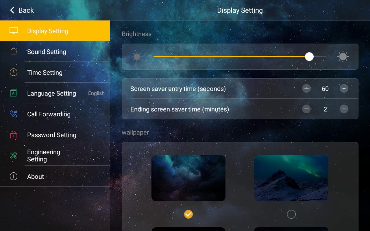
Tap Settings on the main interface to open System Settings, as shown below. System Settings contains Display Setting, Sound Setting, Time Setting, Language Setting, Call Forwarding, Password Setting, Engineering Setting and About. Tap a label to open it.
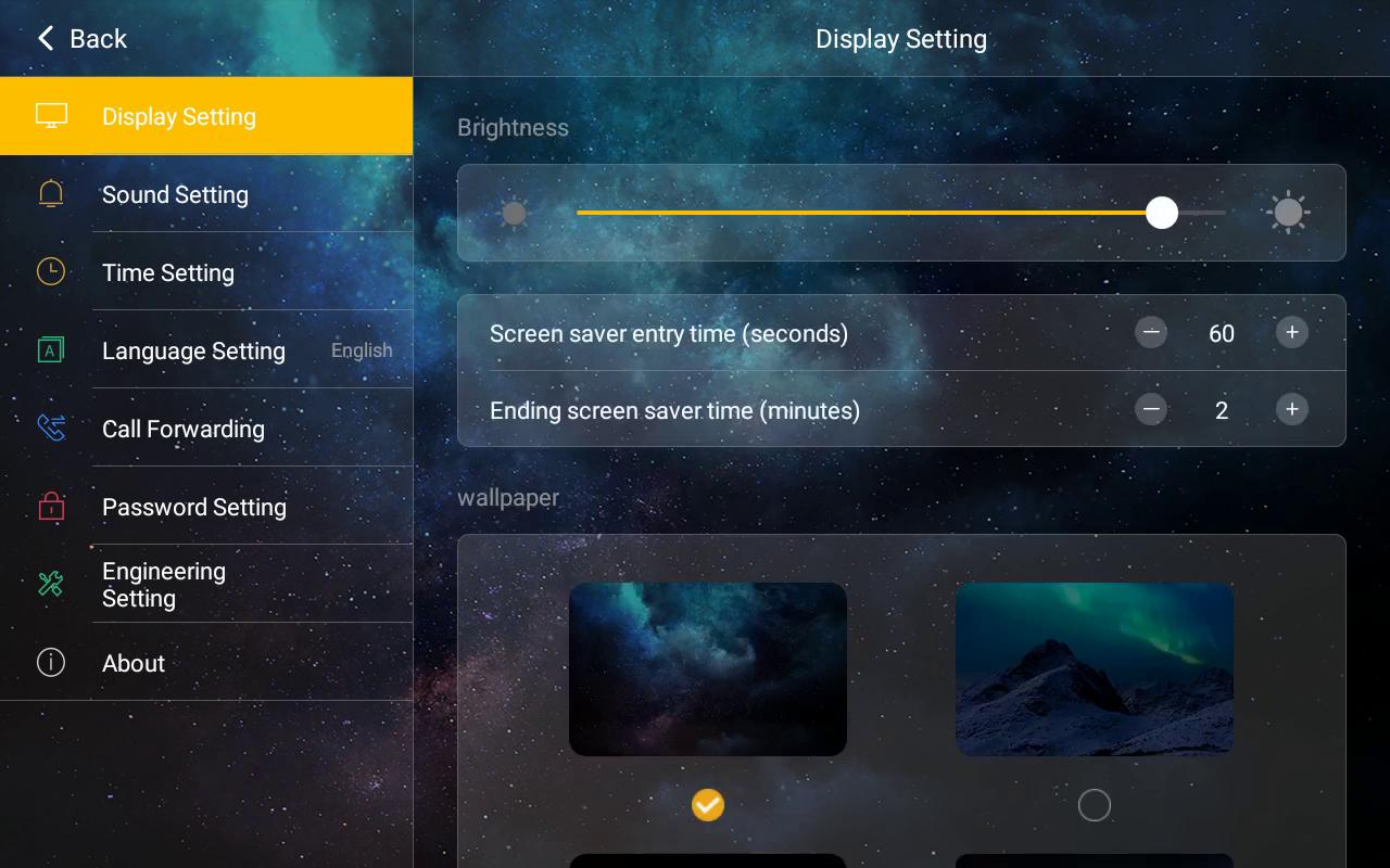
Operation path: Settings > Display Setting
Brightness: brightness is adjustable, by default the brightness is maximum.
Screen saver entry time: the time to enter screen saver is adjustable, range 30 s to 255 s.
Ending screen saver time: the time to end screen saver is adjustable, range 1 min to 10 min.
Wallpaper for screen saver: By default there are four wallpapers, users can import customized wallpaper by using PC configuration tool.
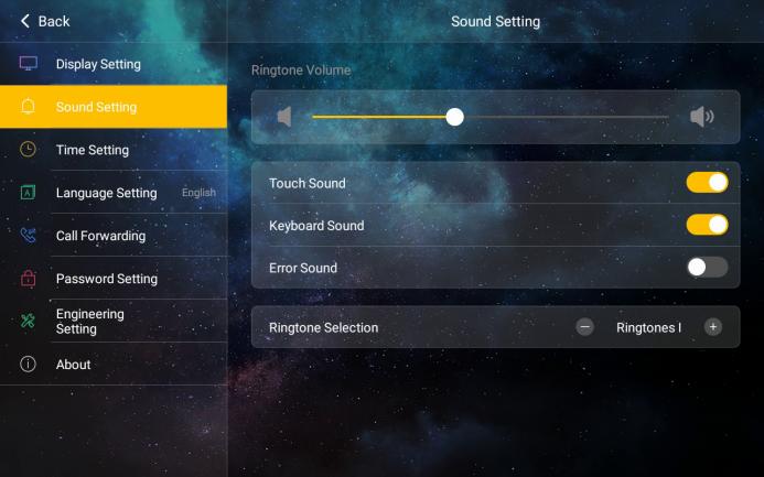
Operation path: Settings > Sound Setting
Ringtone Volume: It’s adjustable.
Touch Sound: Can be enabled and disabled.
Keyboard Sound: Can be enabled and disabled.
Error Sound: Can be enabled and disabled.
Ringtone Selection: By default 5 types of ringtone are selectable.
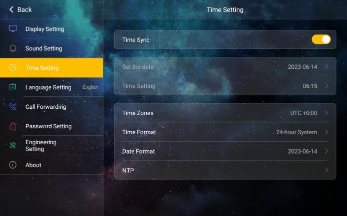
Operation path: Settings > Time Setting
Time Sync: when enabled, automatically synchronizes date and time from the network NTP server according to the set time zone and format. Turn off automatic synchronization and manually set the date and time.
Time Zones: Select the corresponding time zone based on the country you are in. The device converts the local time based on the set NTP server and time zone.
Time Format: Can be 12-hour system or 24-hour system
Date Format: Select the date format as required. Optional date format: Year-Month-Day; Day-Month-Year.
NTP Server: By default, there are 3 built-in NTP servers that users can manually change.
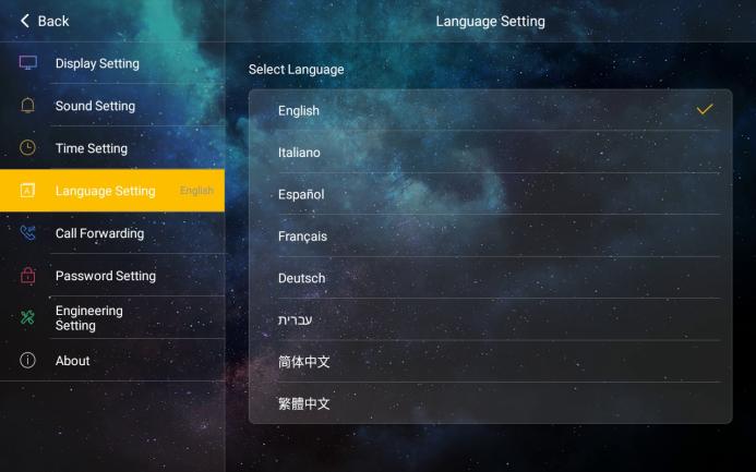
Operation path: Settings > Language Setting
Available in English, Italian, Spanish, French, German, Arabic, Hebrew, Russian, Korean, Vietnamese, Simplified Chinese and Traditional Chinese.
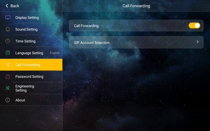
Operation path: Settings > Call Forwarding
Under SIP Account Selection, choose the contact from the address book that receives the forwarded calls. Only one contact can be selected.
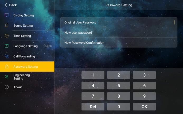
Operation Path: Settings > User Password Setting
User password can be modified, by default the user password is 666666.
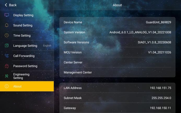
Operation path: Settings > About
Device Name, System Version, Software Version, MCU Version, Center Server
Ethernet Info (LAN, Subnet, Gateway)
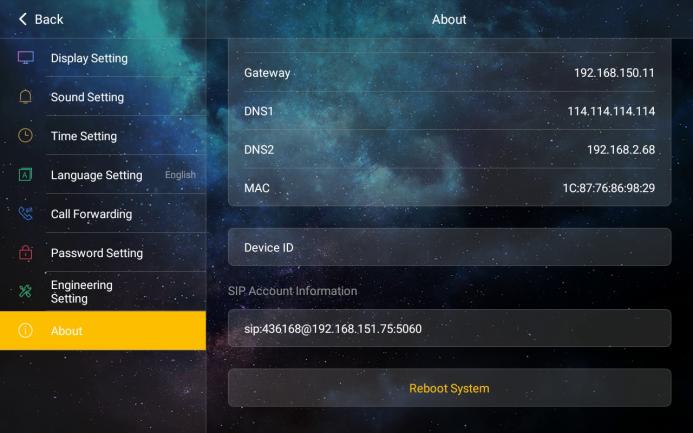
Device ID (A unique identifier for the device)
SIP Account info of Device (SIP Account of the Device, SIP Account 1, SIP Account 2, Cloud SIP Account.)
Reboot System: Click this label to restart the device.
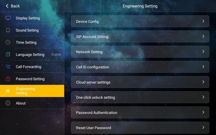
Operation path: Settings > Engineering Setting
Input the Engineering Password 801801 to enter the interface: Device Name, SIP Account Setting, Network Setting, Cell ID configuration, Cloud Server Settings, One Click Unlock Setting, Password Authentication, Reset User Password, Reset Factory Setting.
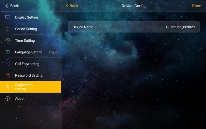
Device Name
Operation path: Settings > Engineering Setting > Device Name
The device name can be changed. To use the SIP account data from the address book, set the device name to the name listed in the address book; a pop-up then asks whether to apply the account data. Large installations use the address book method: one address book is distributed to all devices and the device entries are generated by batch rules.
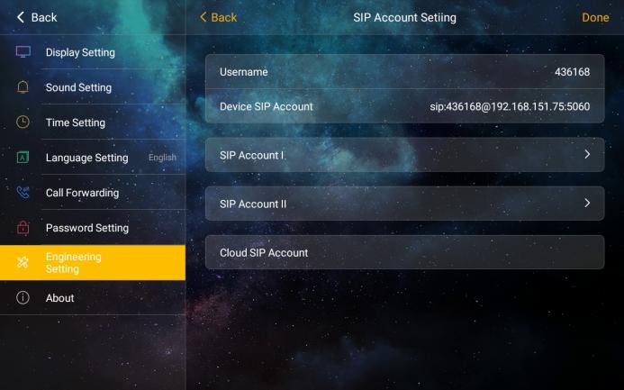
SIP Account Setting
Operation path: Settings > Engineering Setting > SIP Account Setting
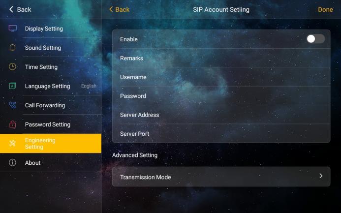
Username: User can call to the Guard Unit by entering the username through the dial keyboard, the username can not be the same as others under the same network.
Local SIP Account of the Device: The username and IP address of the device can generate local SIP Account that’s used as the account being called under the same network.
SIP Account 1&2: User can manually configure SIP account info. Switch on the Enable button, then enter the username, password, server address and server port and select the transmission mode. User can also use the account info of address book by configuring device name.
Cloud SIP Account: After the device connects to the cloud server, the server assigns a cloud intercom SIP account to the device for cloud intercom calls.
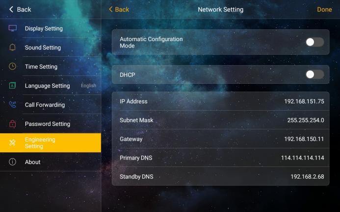
Network Setting
Operation path: Settings > Engineering Setting > Network Setting
Automatic Configuration Mode: After enabled this mode, the device finds the other intercom devices of the same series on the same network.
DHCP: When DHCP is switched off, configure the network manually: IP address, subnet mask, gateway and DNS server.
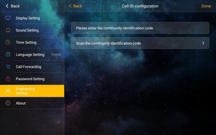
Cell ID Configuration
Operation path: Settings > Engineering Setting > Cell ID Configuration
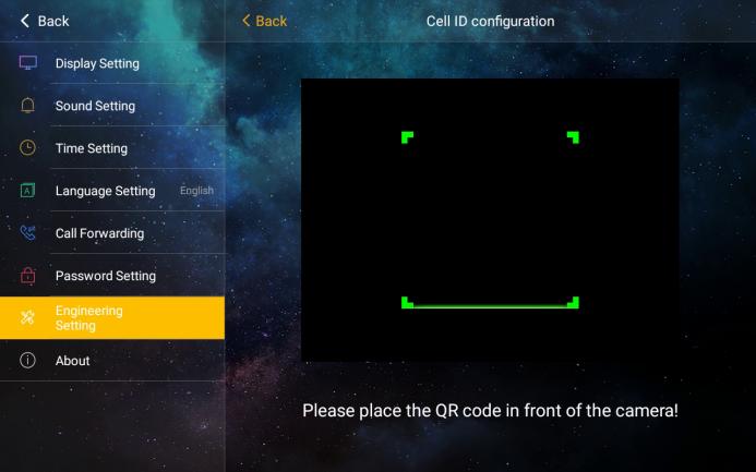
Input the Cell ID or scan the QR code of Cell ID, to bind the device with the community(Cell).
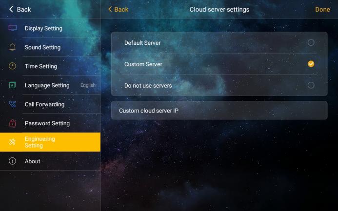
Cloud Server Settings.
Operation path: Settings > Engineering Setting > Cloud Server Settings
Cloud Server Setting is set as Default Server by default; Custom Server is required user to input the address of server manually; NO server is equal to shut down the server. The default server refers to a server deployed on the public network. To connect to this default server, the device must be able to access the external network. A custom server can be a locally deployed server or a regional server, and the device must be able to reach the server over the network.
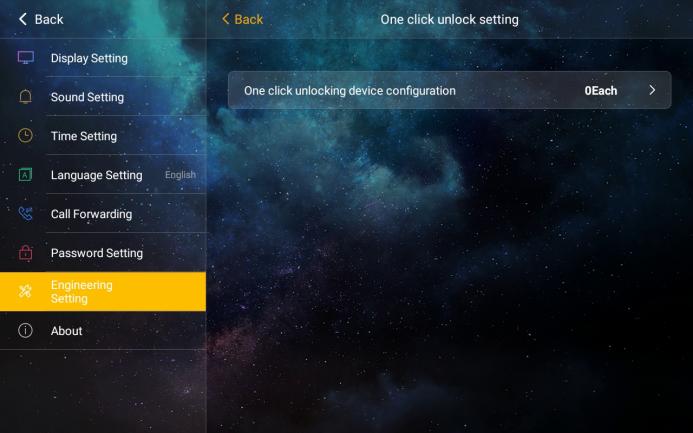
One Click Unlock Setting
Operation path: Settings > Engineering Setting > One Click Unlock Setting
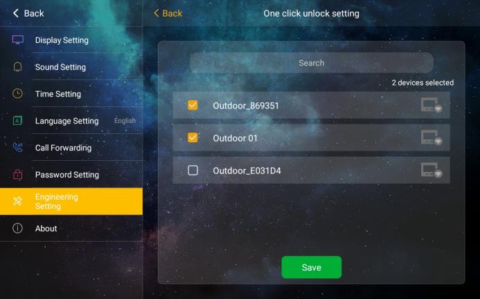
In the list to select which devices that can be unlocked by One Click Unlock function.
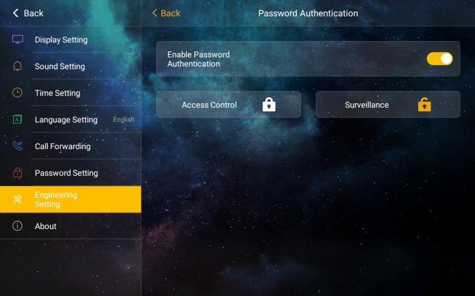
Password Authentication
When Password Authentication is enabled, select the functions to protect; the user password is then required to use them.
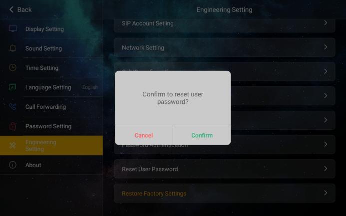
Reset User Password
Operation path: Settings > Engineering Setting > Reset User Password
Once user forgot the user password, user can reset the user password to be 666666.
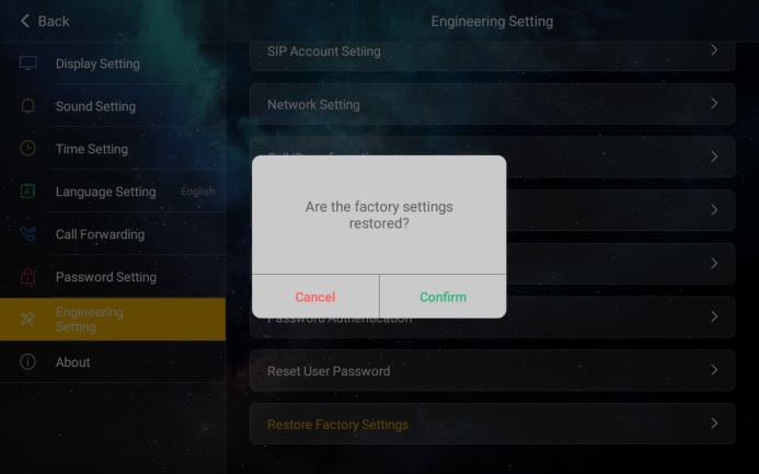
Restore Factory Setting
Operation path: Settings > Engineering Setting >Restore Factory Setting
Restoring the factory settings more than 60 s after power-on resets the device to its default parameters. Restoring them within 60 s after power-on also clears all records.
Automatic configuration mode: This machine can discover other S-series devices in the same network segment. For small systems of up to 16 devices, automatic discovery is preferred: it is plug and play and needs no further configuration. The router allocates IP addresses to the devices, which discover each other with mDNS. Address book mode: To disable automatic configuration mode, address book mode is required. The devices connected to the address book network need to download a unified address book configuration table, which can be pushed locally by Update&Configuration Tool or pulled online from the intelligent management platform.
After receiving the address book, the device restarts and updates its contacts. Go to Engineering Setting – Device Name, enter the device name and tap Save. The device reports that the name exists in the address book and asks whether to use the address book data; confirm, and the device applies the settings and restarts.
Example: the address book contains device "1-1" (region 1, functions: call/monitoring/lift control/access control, IP 192.168.0.20, mask 255.0.0.0, DNS 114.114.114.114 and 8.8.8.8, SIP username 00011, protocol UDP). After entering "1-1" and saving, the IP and SIP settings of the device are updated to these values.
In large installations, set the device name on every device after the address book has been distributed, so that each device applies its own entry.
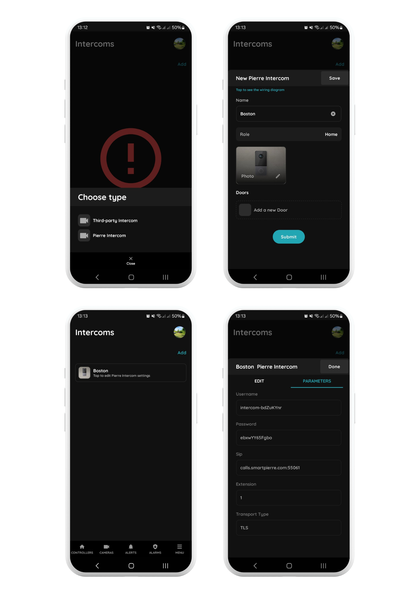
Menu → Intercoms → Add
Select the PIERRE Intercom
Choose the PIERRE Intercom from the list of available devices.
Configure the Intercom Settings
Name: Enter a name for the intercom.
Role: Select the appropriate role for the intercom.
Doors: Select the doors that can be unlocked using the intercom.
Save the Configuration
Click Save to create the intercom. After saving, select the newly created intercom to view or modify its settings.
Access Parameters
Open the Parameters tab to view the configuration settings for the PIERRE Intercom. These parameters are automatically generated by the system and can be modified if required.
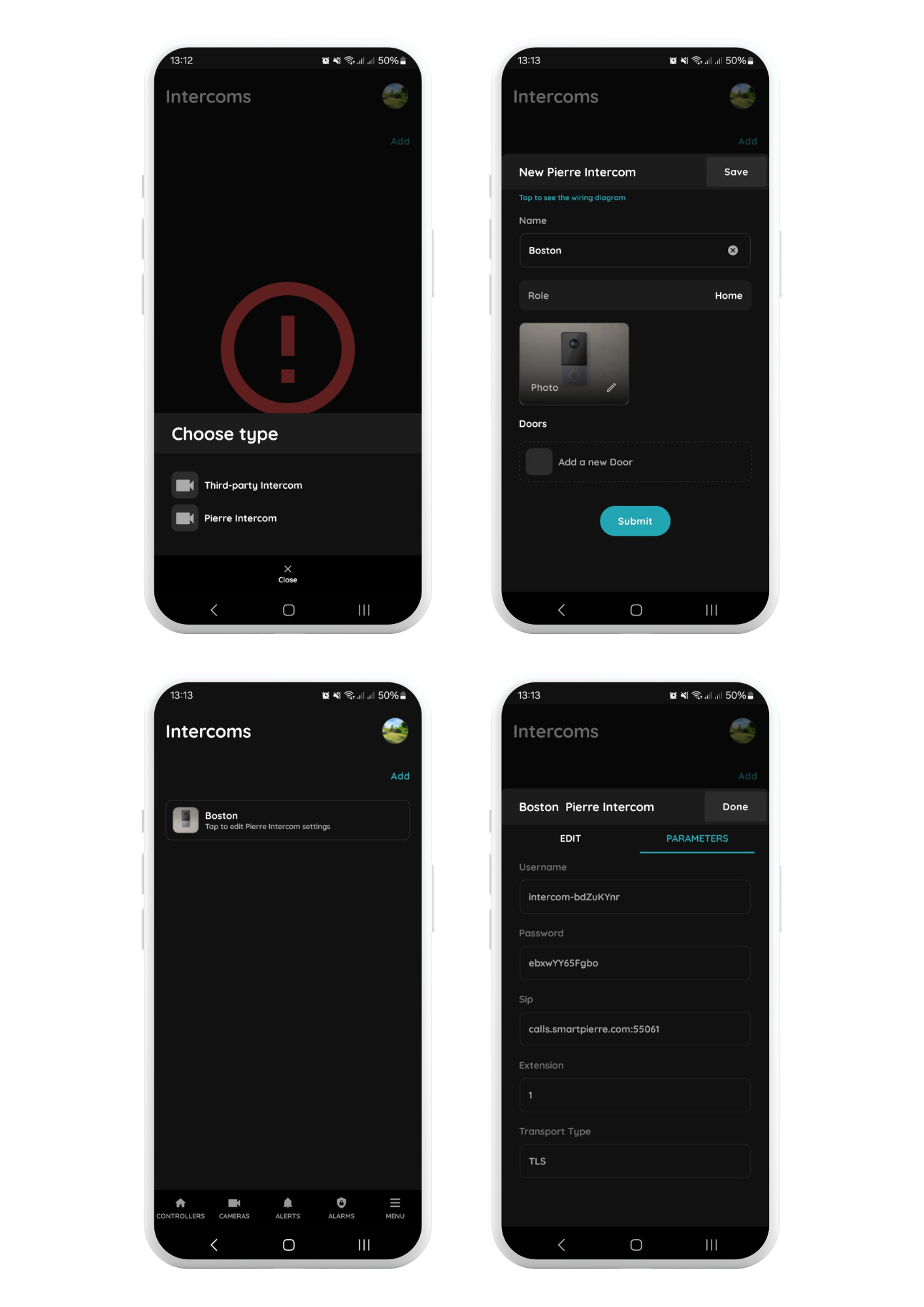
Intercom settings in PIERRE Partner
The following parameters are automatically generated and must be configured in the intercom device (Engineering Setting – SIP Account Setting):
The PIERRE intercom must be added to the Common Controller using a separate role.
Each apartment must have access to the intercom and the corresponding door for remote unlocking. The intercom and the associated door must be assigned to a dedicated role named Intercom and removed from the Default role.
The Intercom role must then be assigned to the PIERRE indoor displays (intercom indoor units) and to the users who should be able to receive and answer intercom calls.
Role and door assignment for the intercom
Yes. Calls between the outdoor intercoms, the Receptionist and the PIERRE displays work locally without internet access. Only remote calls to phones outside the local network need internet.
Depending on the model, PIERRE intercom devices can be powered over Ethernet (PoE). Check the product specifications of your model.
The Receptionist is the management-center unit. Apartments use PIERRE displays as their indoor units; the Smart PIERRE app on a smartphone can also answer calls.
No. Without internet the intercom does not ring on the phone, but it still rings on the Receptionist and the PIERRE displays.