User Manual
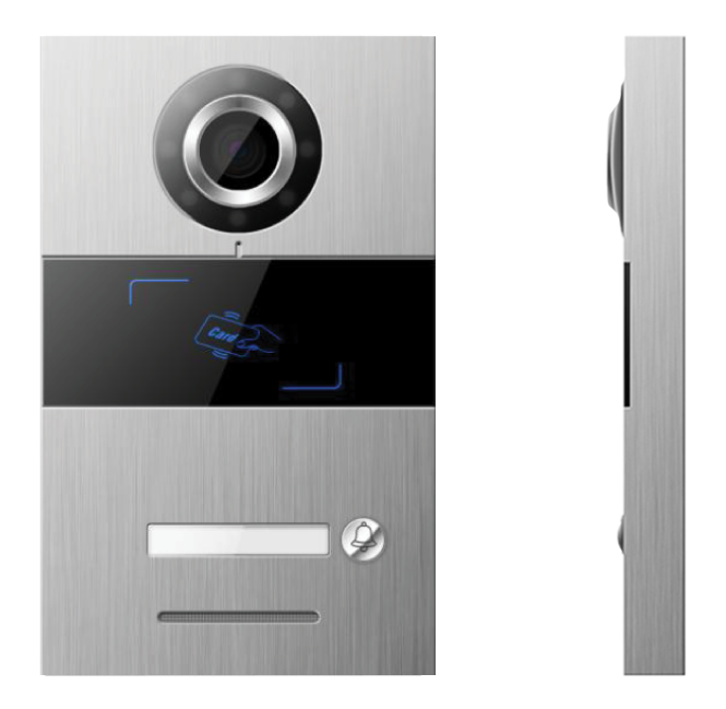
Intercom Springfield (1 Button)
SKU: P-INT-SPRINGFIELD
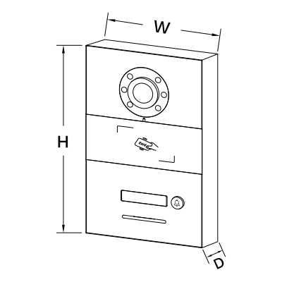
W: 12 cm
H: 19.3 cm
D: 4 cm
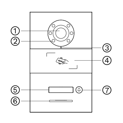
Wired, SIP based. Needs a PIERRE display as the indoor unit (the Smart PIERRE app can also answer calls), a network switch and a DC power supply (see the power input in Product Description).
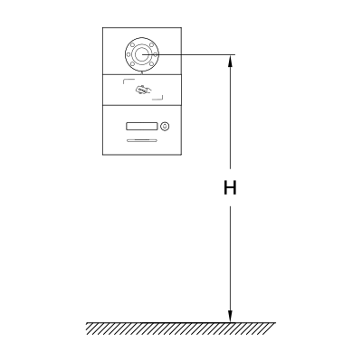
Recommended Installation Height: 1.6 meters - 5.25 feet
H: 1.60 m - 5.25 feet
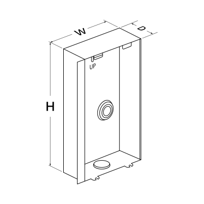
Embedded Box Dimensions
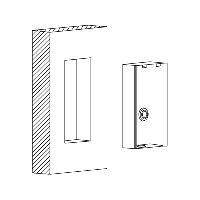
Step 1: Prepare the Wall Slot for the Embedded Box
Cut a slot in the wall that matches the dimensions of the embedded box (100.6 × 175.5 × 39 mm). Ensure the slot is level and deep enough to securely hold the box.
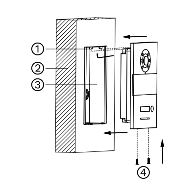
Step 2: Install the Embedded Box
Place the embedded box into the prepared wall slot, ensuring it fits securely. Align it properly, then fasten it using screws to fix it firmly in place.
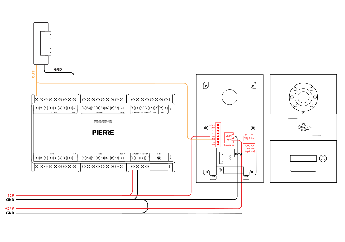
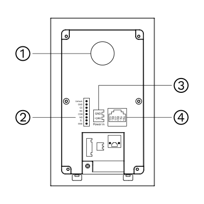
This diagram shows the Springfield intercom wired together with a PIERRE Controller: the intercom relay output (NO/COM) triggers the lock input of the Controller, and the Controller powers the electric lock. The main interfaces of the intercom are:
Note: Always wire with the power off. Installation should be done by qualified personnel.
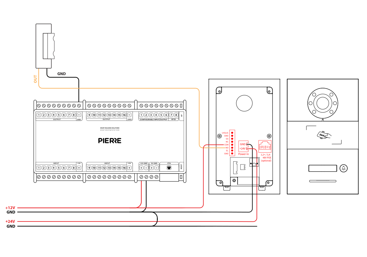
This diagram shows the external wiring setup for connecting the Springfield intercom to peripherals and systems:
Note: Ensure all connections follow polarity and voltage specifications. Only qualified installers should perform wiring.
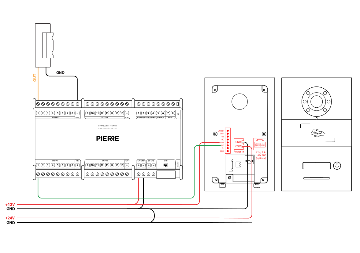
This diagram shows how the Springfield intercom integrates with a door access system:
Note: Always ensure proper voltage and secure connections. Installation must be performed by qualified personnel.
| Run | Wires | Cross-section | Cable type | Conductors |
|---|---|---|---|---|
| From PIERRE to Smart Intercom | 1 | cat.5 | Cat 5e U/UTP | 12 V, GND |
| From Intercom to Network switch | 1 | - | Cat 5e U/UTP | - |
The PIERRE intercoms are SIP-based and work on an offline-first principle: calls are set up over the local network, and remote access is added when an internet connection is available. A dedicated SIP server is not required for local calls.
A network router is a required component of the PIERRE door entry system. The modem-router supplied by the internet service provider is suitable.
Configure the DHCP server range on the router according to the size of the project.
Example – residential building with 50 apartments:
Every PIERRE display needs a fixed IP address. Assign a fixed IP address outside the DHCP range to every display so that the intercom can always reach it.
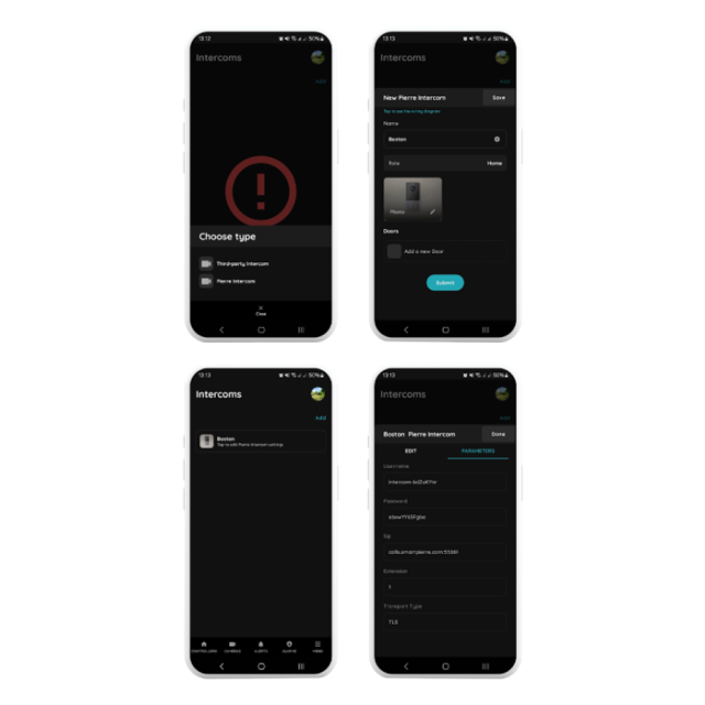
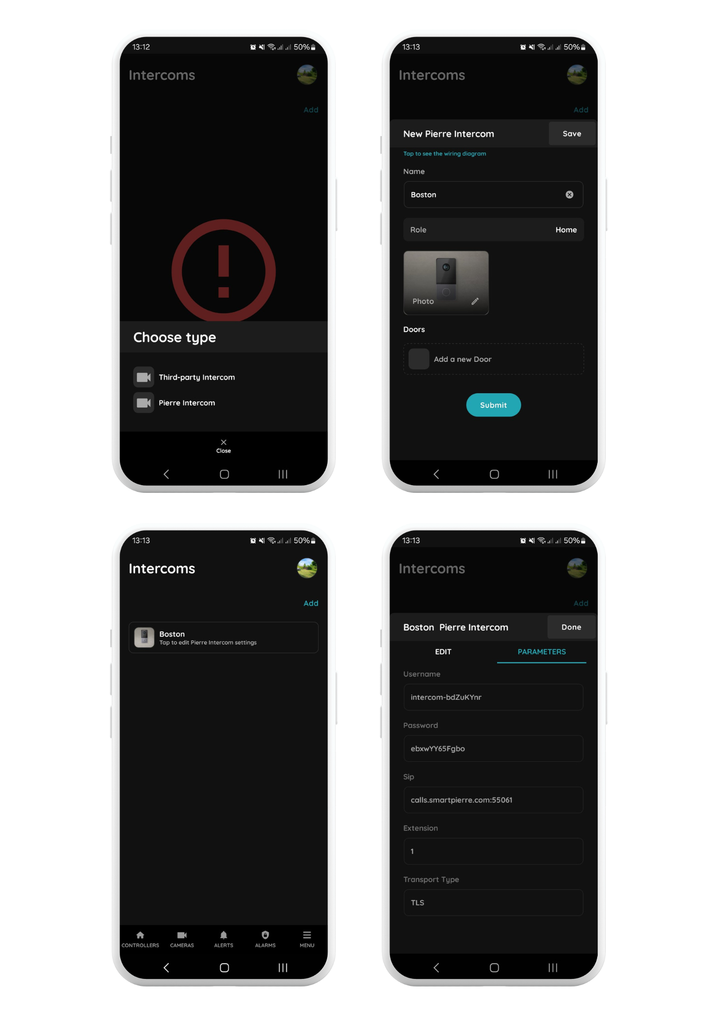
Menu - Intercoms - Add
Select the PIERRE Intercom
Choose the PIERRE Intercom from the available options.
Configure the Intercom Settings
Save the Configuration
After saving, click on the newly created intercom to view or modify its settings.
Access Parameters
Navigate to the Parameters tab to find the configuration settings for the PIERRE Intercom. These settings are automatically generated by the system and can be adjusted as needed.
Important: Change the default login credentials at the end of the setup process and record the new details securely.
In the intercom’s web interface, set up the following parameters under SIP Account Settings:
Step 1: Open the network settings
Step 2: Set Ethernet to a static address
Step 3: Assign the fixed IP address
Step 4: Router
Example configuration for smaller projects (up to 45 apartments)
Router DHCP server start address: set the DHCP server to distribute addresses from, for example, 192.168.1.101.
Static IP range for displays: assign static addresses below the DHCP range, for example:
This avoids IP conflicts between the displays and the DHCP clients.
Prerequisite:
Ensure the target device (Indoor Monitor or Guard Unit) has been configured as the called party using the configuration tool.
Operation:
During the Call:
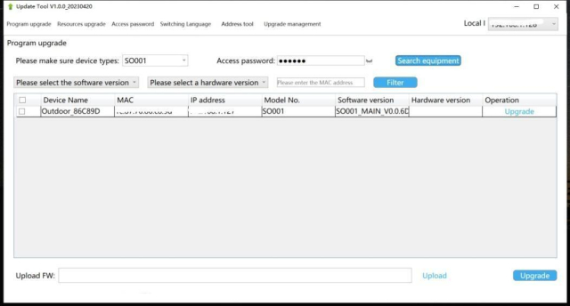
Follow the steps below to configure the Springfield intercom using the configuration tool:
Step 1: Launch the Configuration Tool
Step 2: Switch Language (Optional)
Step 3: Device Search
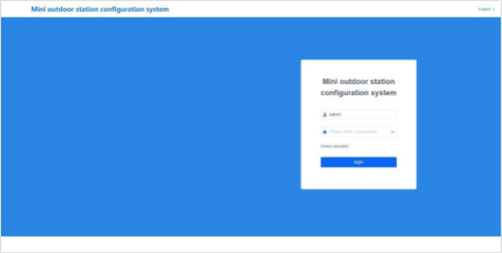
Step 4: Access the Web Configuration Page
Important Note:
Ensure that the computer's IP address and the device's IP address are on the same network segment to allow successful communication and configuration.
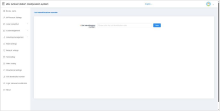
The device name can be modified to suit your system configuration.
If you intend to use SIP account information from the address book, the device name must match the name associated with the SIP account in the address book.
After entering the device name, the system will prompt you with a pop-up window asking whether to use the corresponding account information from the address book.
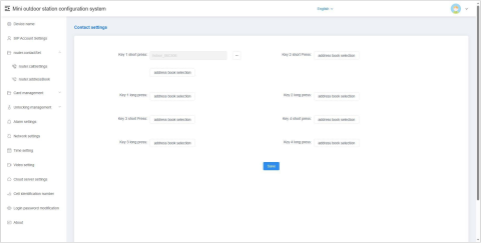
This setting allows you to configure the called party for the button on a single outdoor unit.
This enables flexible calling behavior depending on how the button is used.
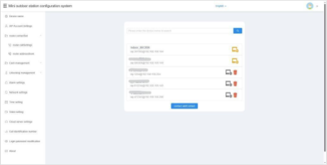
This section displays information about all current contacts. Contacts may include:
Add
You can add a new contact to the local device by entering the following information:
Delete
You can delete contact entries from the list.
Note:
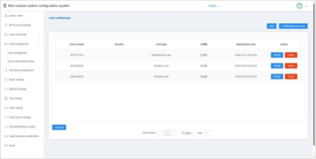
Use the configuration tool to register, modify, delete, or clear access card information on the local device.
In default server or custom server mode, card data is automatically synchronized with the platform. The device supports up to 20,000 access cards.
Single Addition
Continuous Addition
Modification
Deletion
Empty
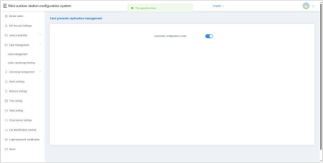
When this option is enabled, all newly registered access cards will be encrypted, making them non-copyable. This enhances security by preventing unauthorized duplication of cards.
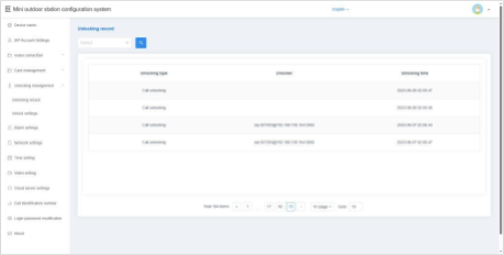
This feature allows you to view the unlock history of the device. Each record includes details of the unlocking method, time, and user or device involved, providing a clear audit trail for security monitoring.
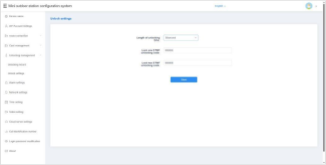
Unlocking Time
You can configure the duration the door remains unlocked after an unlock command is issued.
Lock 1 / Lock 2 DTMF Unlock Password
Set the DTMF unlock password for Lock 1 and Lock 2.
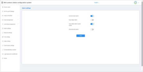
Tamper Alarm
When enabled, the device will sound an alarm tone if it is physically tampered with or removed by external force.
Disconnection Alarm
When enabled, the device will emit an alarm tone if it becomes disconnected from the network.
Additionally, a disconnection icon will appear in the status bar.
Door Status Alarm & Alarm Tone
When enabled, if the door remains open for more than 120 seconds, the device will trigger an alarm tone to alert users of the abnormal door status.
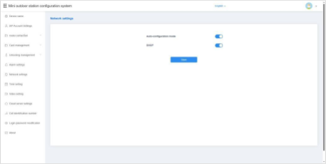
Automatic Configuration Mode
When enabled, the device can automatically discover other intercom devices of the same series within the same network segment. This simplifies device integration and communication.
DHCP
When DHCP is disabled, you must manually configure the network settings. Enter the following parameters:
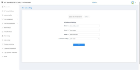
Refresh
After modifying the NTP server or time zone settings, click Save, then click Refresh. This allows the device to update and synchronize its local time with the configured settings.
NTP Server Setup
Enter the address of an NTP (Network Time Protocol) server to enable the device to automatically obtain accurate clock time.
Time Zone Setting
Select the appropriate time zone based on your country or region. The device will adjust the local time according to the selected time zone and the NTP server data.
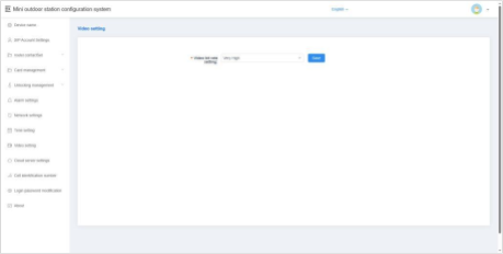
This option allows you to configure the video bit rate used during calls and monitoring. Adjusting the bit rate helps balance video quality and network performance based on your specific environment and bandwidth availability.
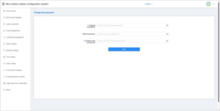
This option allows you to change the login password used to access the device’s configuration interface.
It is recommended to set a strong, secure password to protect the device from unauthorized access.
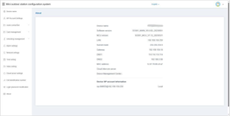
The About section provides detailed information about the device, including:
This information is useful for network configuration, troubleshooting, and technical support.
The PIERRE intercom must be added to the Common Controller using a separate role.
Each apartment must have access to the intercom and the corresponding door for remote unlocking. The intercom and the associated door must be assigned to a dedicated role named Intercom and removed from the Default role.
The Intercom role must then be assigned to the PIERRE indoor displays (intercom indoor units) and to the users who should be able to receive and answer intercom calls.
Role and door assignment for the intercom
Yes. The intercom works locally without internet access. Calls still ring on the PIERRE display, but you cannot receive intercom calls remotely from outside the local network.
Depending on the model, the intercom can be powered over Ethernet (PoE). Check the product specifications of your model.
No. PIERRE displays work as the indoor intercom unit, so a separate indoor unit is not needed. The Smart PIERRE app on a smartphone can also answer intercom calls.
No. Without internet the intercom does not ring on the phone, but it still rings on the PIERRE display.