User Manual
PIERRE Pro - EV Charger 22kW Three Phase (6-32A) - PREORDER
SKU: PP-EVC32A
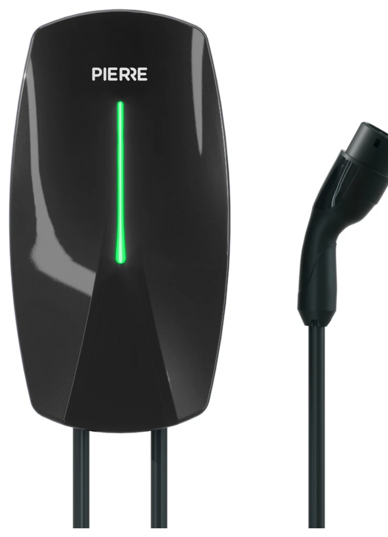
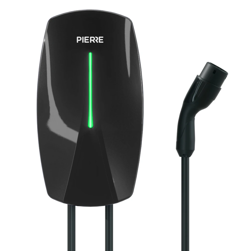
Three-phase AC EV charger with 22 kW nominal output, adjustable current (6–32 A), OCPP 1.6 compatibility, and multi-level protection features. Designed for fixed installation in residential and commercial settings, with Type 2 and GB/T connectors.
The EV Charger is monitored and controlled from the Smart PIERRE app. The charger communicates with the PIERRE cloud over OCPP 1.6 (Open Charge Point Protocol), which provides remote management, status monitoring and charging session control.
The integration enables features such as:
The EV Charger supports two operating modes.
In Plug & Play mode, charging starts automatically as soon as the vehicle is connected to the charger. No user authentication is required. Use this mode only where access to the charger is physically restricted to authorized users.
In Authorization mode, users must authenticate before a charging session can begin. Authentication is performed with an RFID card, so only authorized users can start a session. This mode is recommended for apartment buildings, workplaces, hotels, public parking areas, and other shared charging locations where access control and user identification are required.
An EV charger is a high-power electrical device and must be installed according to local electrical regulations by a qualified electrician.
Before installation, the following requirements must be verified:
Improper installation may result in overheating, equipment damage, or electrical hazards. Always ensure that the electrical installation complies with local regulations and that the available electrical capacity is suitable for the selected charger and charging current. Installation and commissioning should only be performed by qualified personnel.
Keep these instructions. Read them fully before you install or use the charger.
Warning
Wired and cloud connected. Needs an internet connection for OCPP communication with the PIERRE cloud; no PIERRE Controller is required. Controlled through the Smart PIERRE app.
| CE Marking | Yes |
| Warranty | 2 years |
| Operating Temperature | -22 - +122 °F |
| Operating Temperature (°C) | -30 - +50 |
| Operating Humidity | 5 - 95 % RH |
| Altitude | <2000 m |
| IP Rating | IP65 |
| LED Indicators | Yes |
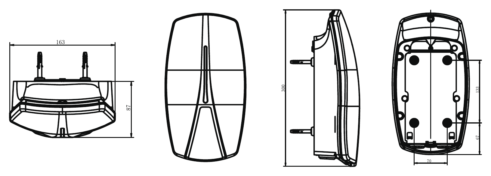
| Width | 163 mm |
| Height | 330 mm |
| Depth | 87 mm |
| Weight | 5000 g |
| Panel Material | ABS+PC material |
| Product Color | Black |
| Connectivity | 2.4GHz Wi-Fi (802.11 b/g/n) |
| Communication Frequency | 2.4GHz |
| Safety Features | Overload protection, Over voltage protection, Short circuit protection, Thermal protection |
| Input Voltage | AC 380 - 400 V |
| Current | 32 A |
| Frequency | 50-60Hz |
| Access Modes | Smartphone, Card (EM & Mifare) |
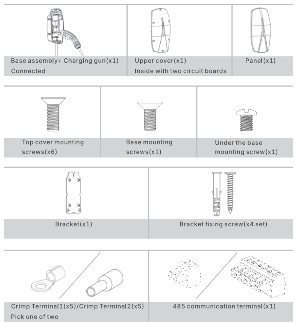
Unpack the charger and check that the box contains the following items.
Use either the ring or the ferrule crimp terminals, depending on your wiring.
Check the charger for transport damage. If anything is missing or damaged, contact your PIERRE partner before installation.
| Item | Quantity |
|---|---|
| Charger base with charging cable and Type 2 connector (pre-assembled) | 1 |
| Upper cover (with two circuit boards inside) | 1 |
| Front panel | 1 |
| Top cover mounting screws | 6 |
| Base mounting screw | 1 |
| Under-base mounting screw | 1 |
| Wall bracket | 1 |
| Bracket fixing screws with wall plugs | 4 sets |
| Crimp terminals - ring type | 5 |
| Crimp terminals - ferrule type | 5 |
| RS485 communication terminal | 1 |
Who may install the charger
Only a qualified electrician may install, operate and maintain the charger: a person with certified electrical training who knows the applicable regulations and the hazards involved.
Choosing the location
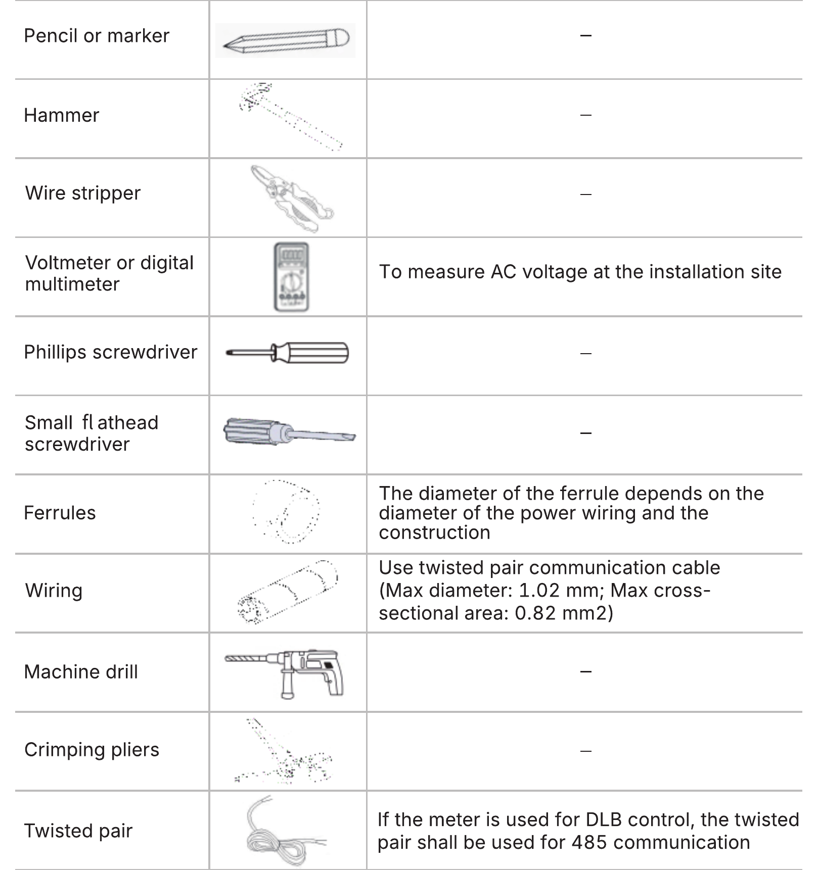
Tools you need
Switch off the circuit breaker before you start. Check with the multimeter that the supply cable is not live.
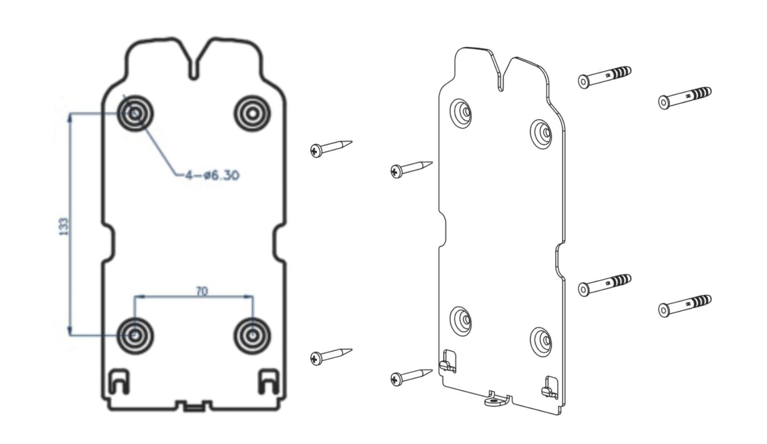
Step 1 – Fix the wall bracket
Hold the bracket against the wall and mark the four holes. Drill the holes to the size shown on the bracket, insert the wall plugs, then screw the bracket firmly to the wall with the four bracket screws.
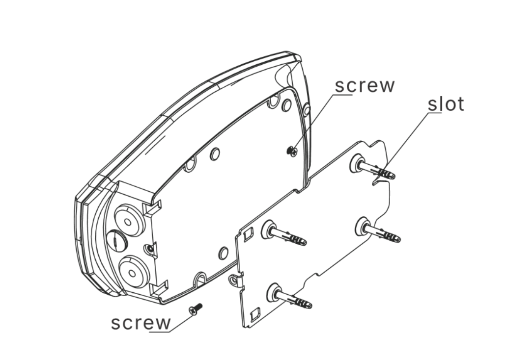
Step 2 – Hang the charger body on the bracket
Hang the charger body on the bracket so the slots sit on the bracket hooks. Secure it with the base mounting screw and the under-base mounting screw.
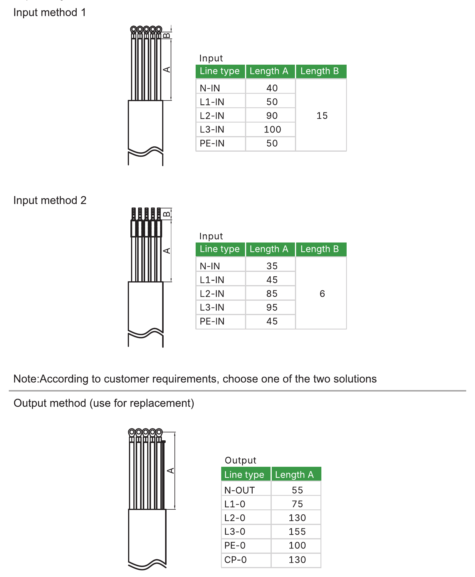
Step 3 – Connect the supply cable
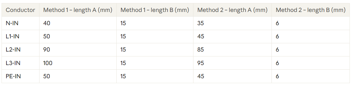
Strip the supply cable and its conductors to the lengths below. Choose the method that fits your cable entry; both are valid.
Crimp a terminal onto each conductor and connect it to the matching input terminal on the circuit board.
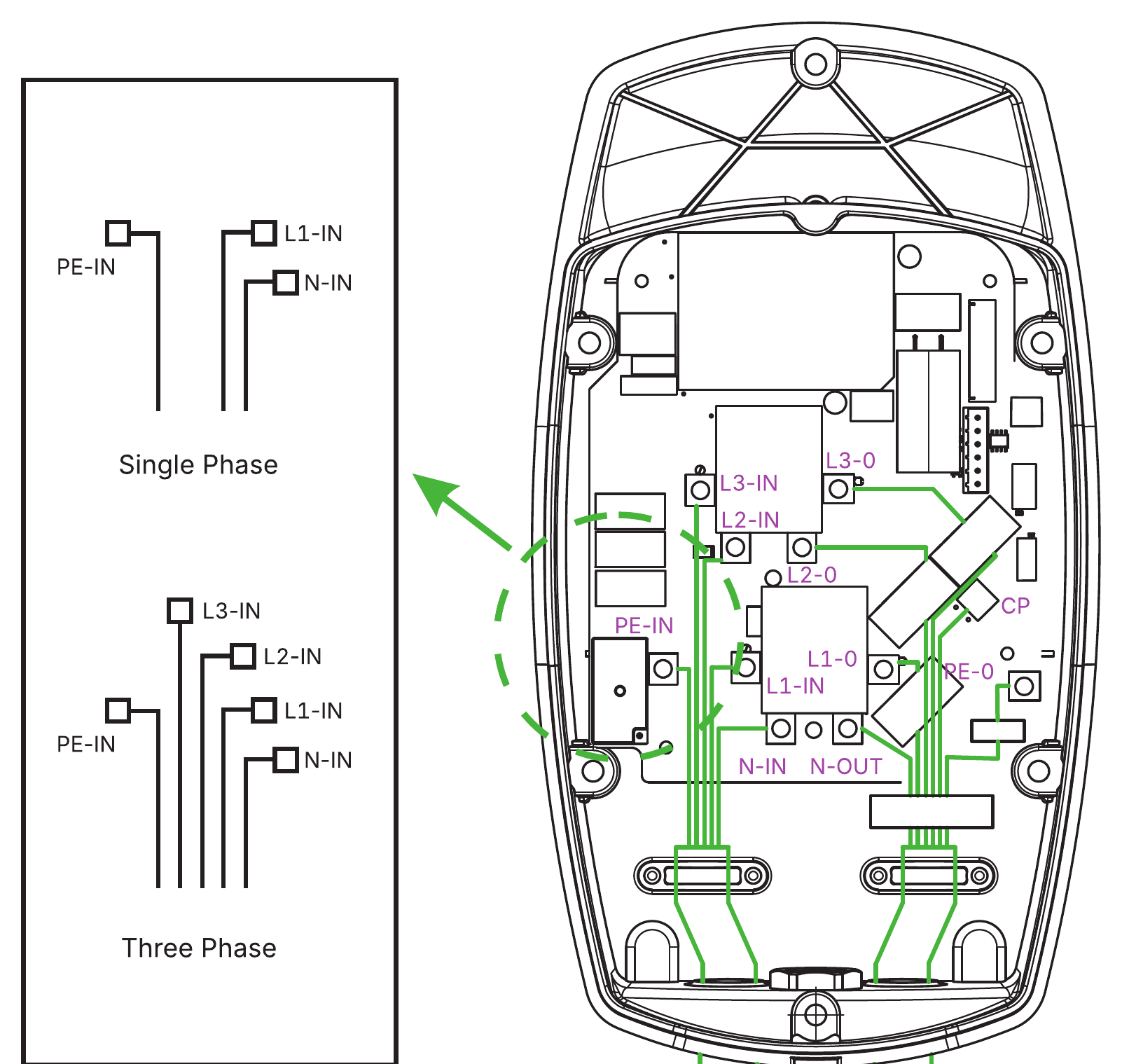
If you ever replace the charging cable, strip its conductors to: N-OUT 55 mm, L1-O 75 mm, L2-O 130 mm, L3-O 155 mm, PE-O 100 mm, CP-O 130 mm.
Step 4 – Connect dynamic load balancing (optional)
See section 7.
Step 5 – Set the charging current
See section 6.
Step 6 – Connect the upper cover
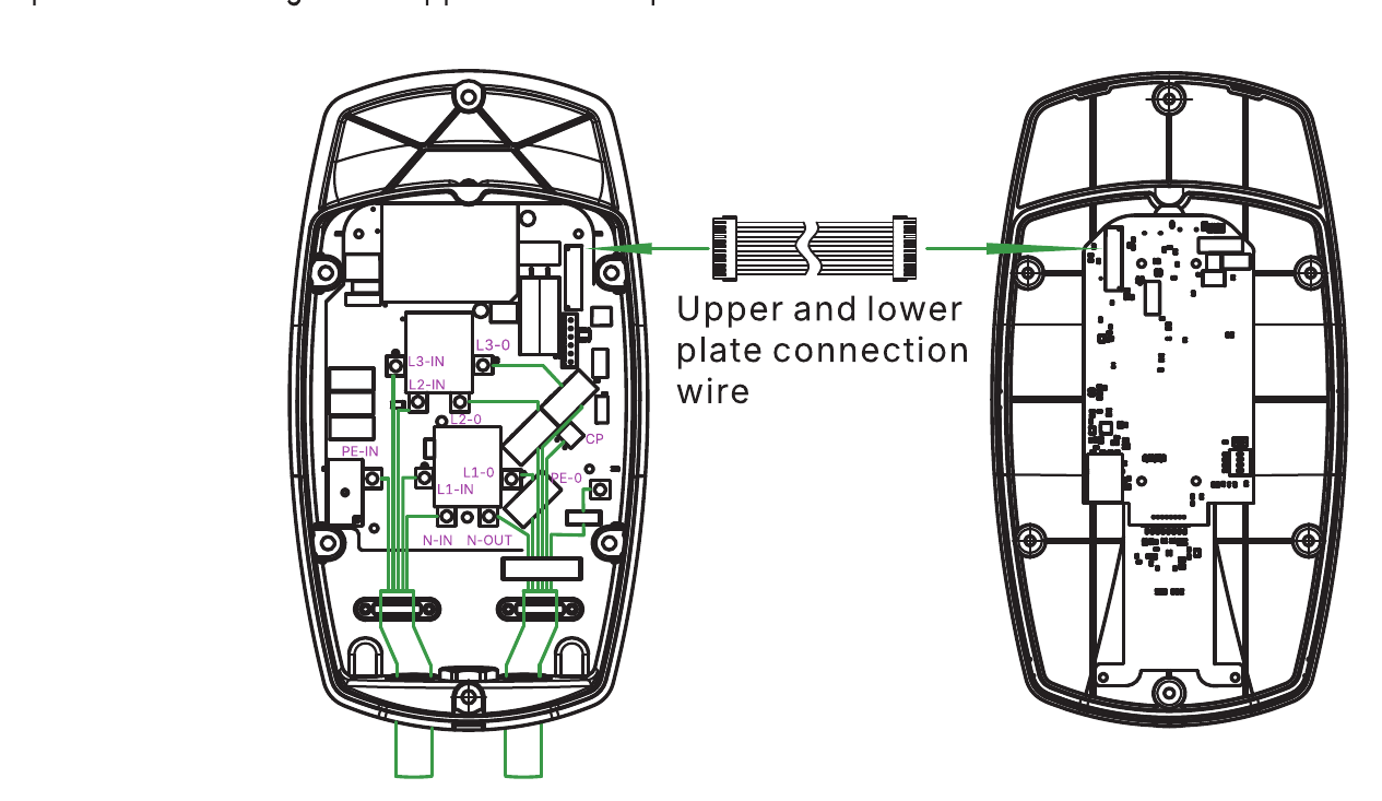
Plug the connection cable between the circuit board in the base and the circuit board in the upper cover.
Step 7 – Fit the upper cover
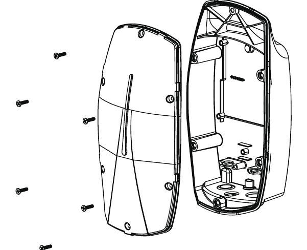
Place the upper cover on the base and fasten it with the six top cover screws.
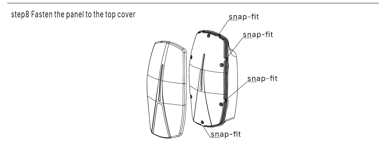
Step 8 – Fit the front panel
Press the front panel onto the upper cover until all snap-fits click into place.

Removing the front panel
Release snap-fit A at the bottom, then snap-fits B on the left and right, and push the panel upwards.
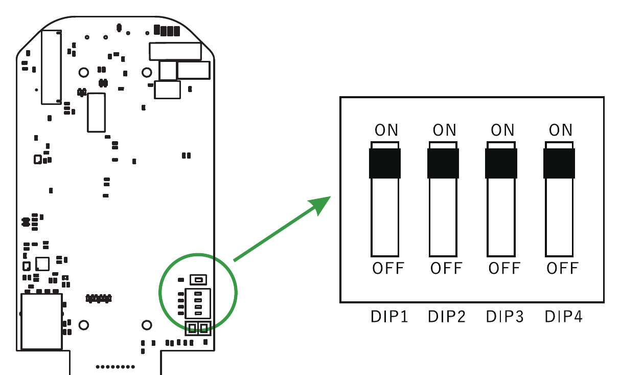
The four DIP switches on the circuit board set the maximum charging current and two operating options.
Warning: the power must stay OFF while you change the DIP switches. Changes made with the power on are not applied, and touching the board under power can cause an electric shock.
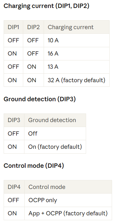
DIP switch settings:
Charging current (DIP1, DIP2)
Ground detection (DIP3)
Control mode (DIP4)
Before you switch the charger on for the first time, check the following.
Switch on the circuit breaker. The LED runs a self-check (blue, green and red flash alternately) and then shows a steady blue light: the charger is in standby.
| LED | Status |
|---|---|
| Blue - green and red flash alternately | Self-check after power-on |
| Blue - steady | Standby |
| Blue flashing | Connecting to the vehicle |
| Green steady | Charging |
| Red steady | Over-temperature protection |
| Red 3 fast + 1 slow | Over-current protection |
| Red 3 fast + 2 slow | Residual current (leakage) protection |
| Red 4 fast + 1 slow | Under-voltage protection |
| Red 4 fast + 2 slow | PEN fault protection |
| Red 5 fast + 1 slow | Over-voltage protection |
| Red 6 fast + 1 slow | Contactor welding protection |
| Red 7 fast + 1 slow | Ground fault protection |
| Red 8 fast + 3 slow | Electronic lock fault |
Slow flash: 2 s on, 0.5 s off. Fast flash: 0.5 s on, 0.5 s off.
If the LED shows red, unplug the vehicle, switch the charger off at the circuit breaker, wait 30 seconds and switch it on again. If the fault remains, contact your PIERRE partner.
Connect the vehicle
Start charging
Hold your RFID card against the card reader on the front panel, or start the session in the app. The LED turns steady green and charging begins.
Stop charging
Charging stops automatically when the battery is full. To stop earlier, hold your RFID card against the reader again or stop the session in the app. Wait until the LED returns to blue, then unplug the connector from the vehicle and hang the cable on the charger.