User Manual
Power Supply 12V/1.25A (DIN)
SKU: PP-PWR-125A-DIN
Wired. Mains AC input, DIN-rail mounted. Provides 12 V DC for PIERRE devices such as the Controller; size the supply to the total current of everything connected.
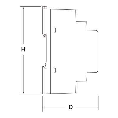
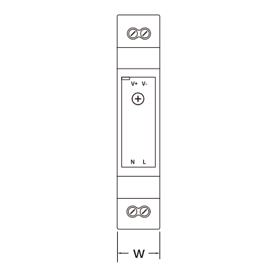
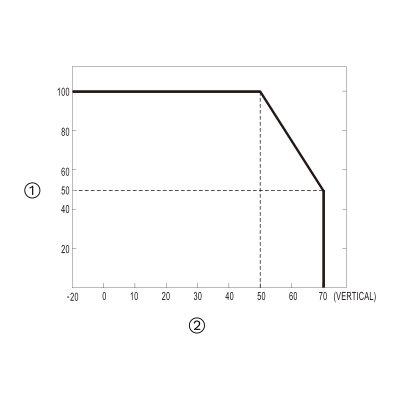
| Operating Temperature | -4°F ~ +158°F |
| Operating Temperature (°C) | -20°C ~ +70°C |
| Operating Humidity | 20%-90% RH, Non Condensing % RH |
| Storage Temperature | -40°C - +80°C |
| IP Rating | IP20 |
| LED Indicators | Yes |
| Safety Features | Overload protection, Over voltage protection, Short circuit protection |
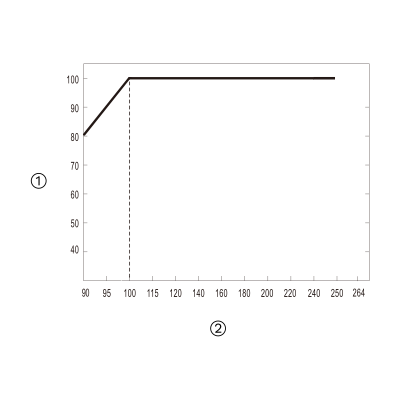
| Input Power | 100-240V AC |
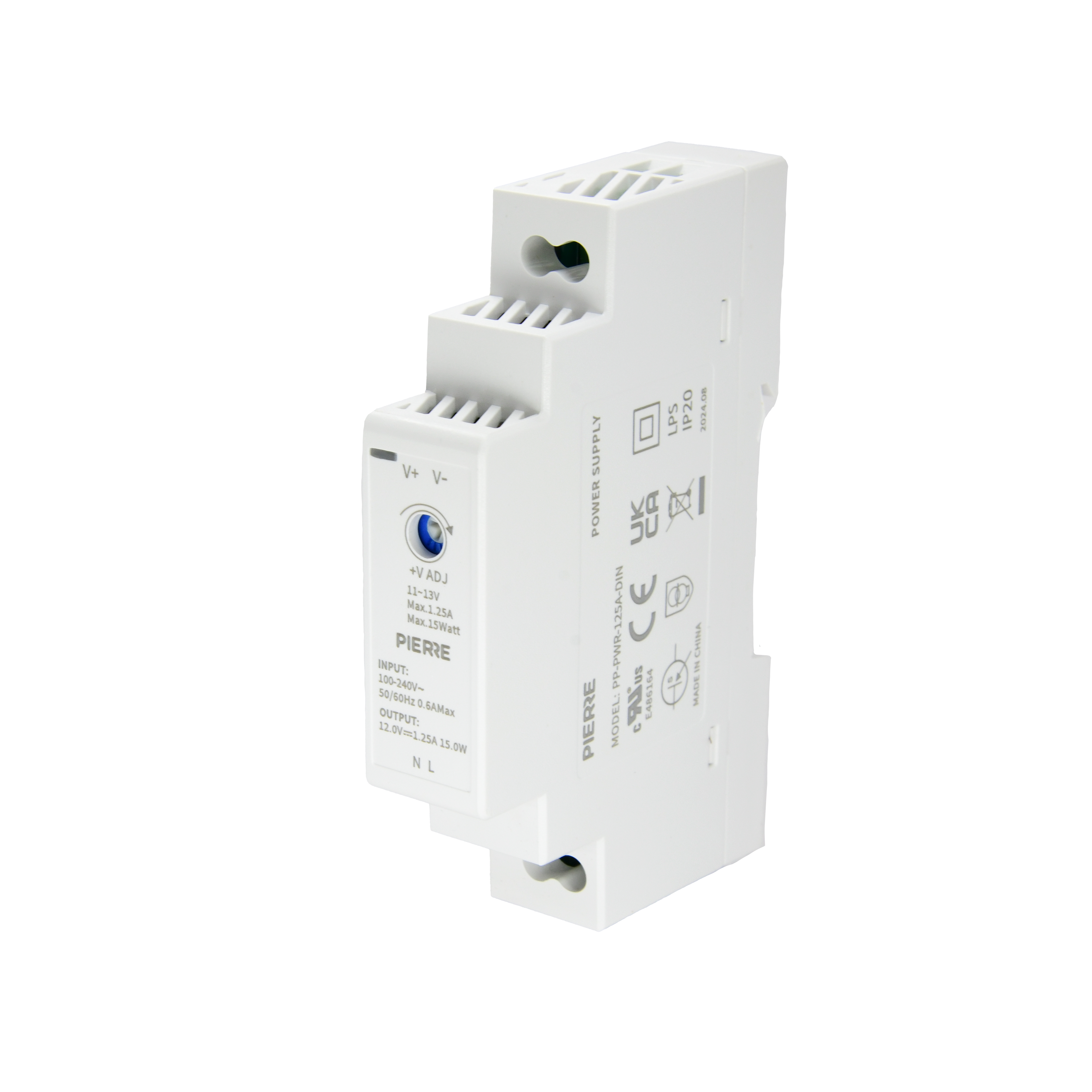
| Output Power | 12V DC 1.25A 15W |
| Efficiency | 85 % |
| Power Factor | 0.98 |
| Current | 1.25 A |
| Product Color | White |
| Mounting Type | DIN Rail |
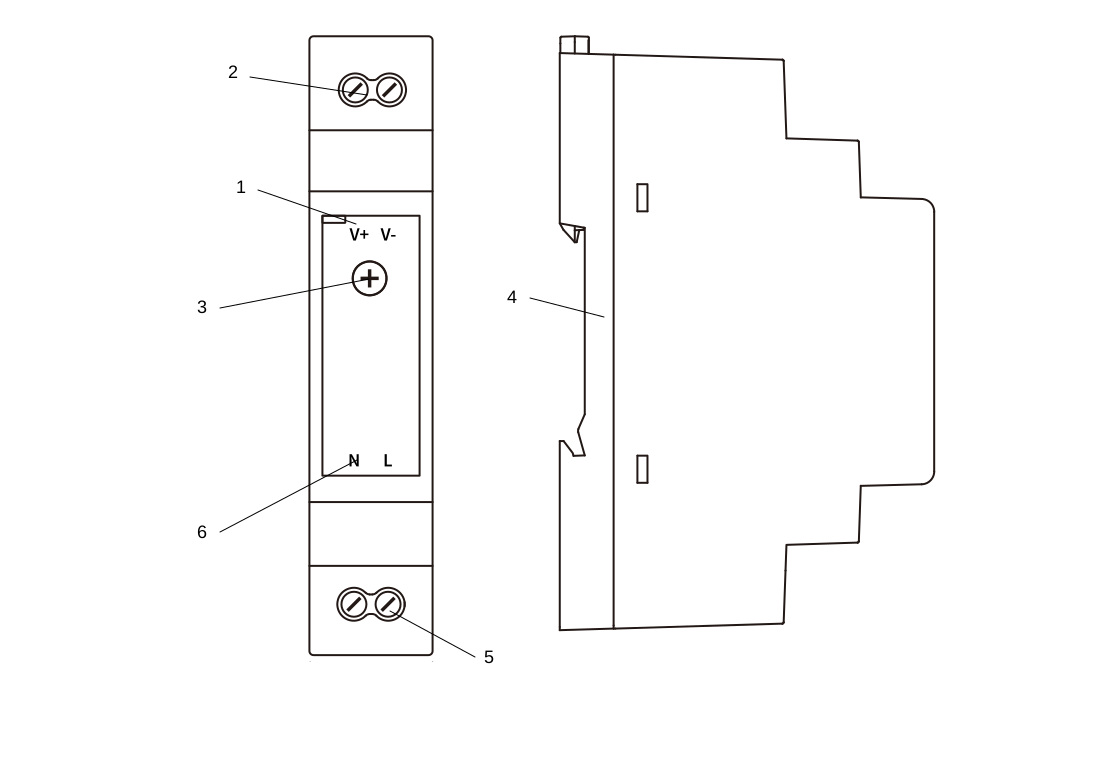
| Wiring Requirements | N - Neutral, L - Live |
| Run | Wires | Cross-section | Cable type | Conductors |
|---|---|---|---|---|
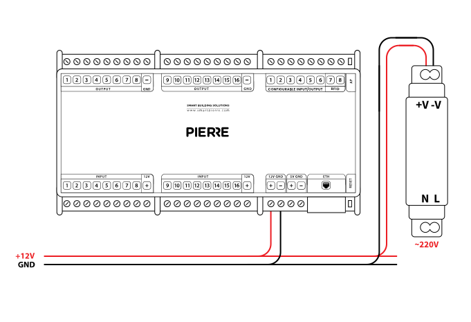
| Example: From power supply to Controller | 2 | 0.75 mm² | NYM-J | +12 V, GND |
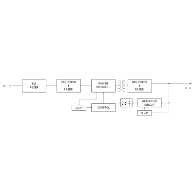
Functional Diagram – System Overview
The diagram shows the internal stages of a switching mode power supply (SMPS) from AC input to regulated DC output.
Block descriptions: