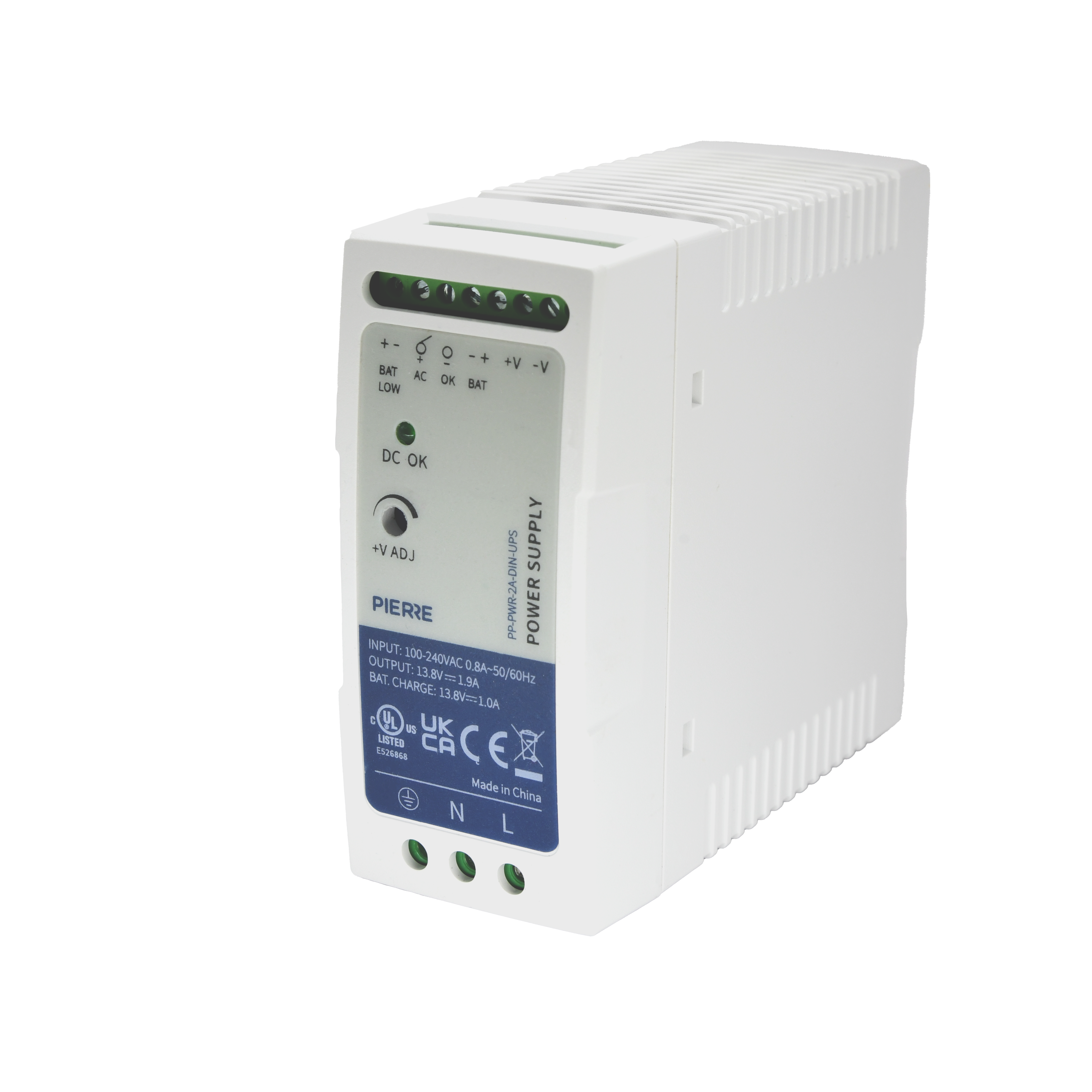
Power Supply 12V/2A (DIN, UPS)
User Manual

Power Supply 12V/2A (DIN, UPS)

SKU: PP-PWR-2A-DIN-UPS

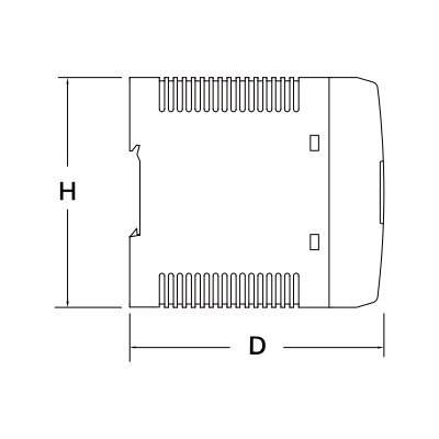
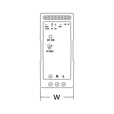
1. Dimensions

Image
  • D: 100 mm
  • H: 92 mm
Image
  • W: 41 mm

2. What you need

Wired. Mains AC input, DIN-rail mounted. Provides 12 V DC for PIERRE devices such as the Controller; size the supply to the total current of everything connected.

3. Wiring

Image
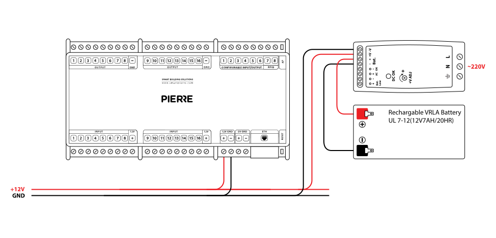
  • Connect the L and N terminals of the power supply to the AC mains (Live and Neutral).
  • The DC output terminals +V and −V supply 12 V DC to the connected device.
  • Connect a rechargeable VRLA battery to the Bat.+ and Bat.− terminals; observe the polarity.
  • The battery charges while mains power is available and supplies the load during an outage.
Run Wires Cross-section Cable type Conductors
Example: From power supply to Controller 2 0.75 mm² NYM-J +12 V, GND

4. Block Diagram

Image

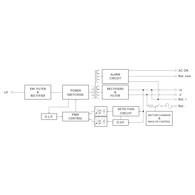
Power Supply with Battery Backup – Functional Description

The block diagram shows the internal structure of a power supply unit with battery backup:

  • EMI Filter & Rectifier: filters electromagnetic interference from the input and converts AC to DC.
  • Power Switching: converts and regulates the voltage by high-speed switching.
  • Rectifiers & Filter: smooths and stabilises the output voltage for the load.
  • PWM Control: controls the switching to keep the output constant (pulse width modulation).
  • O.L.P. (Over Load Protection): shuts down or limits the output when an excessive load is detected.
  • O.V.P. (Over Voltage Protection): cuts the output if the voltage exceeds the safe limit.
  • Detection Circuit: monitors voltage and other parameters to trigger protective actions or status indicators.
  • Battery Charger & Backup Control: manages battery charging and switches to battery power when the mains fails.
  • Alarm Circuit: indicates system status: AC OK (input power is normal), Bat. Low (battery voltage is low).
  • Output Terminals: +V / -V main output to the load; Bat. + / Bat. - battery connection terminals.
5. Derating Curve

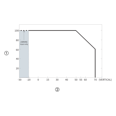
Image
  1. Load (%)
  2. Ambient Temperature (°C)

6. Output Derating vs Input Voltage

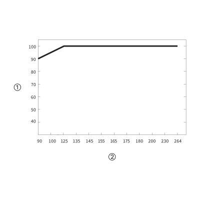
Image
  1. Load (%)
  2. Input voltage (V AC), 60 Hz

7. Side Notes

  • All parameters not specially mentioned are measured at 230 V AC input, rated load and 25 °C ambient temperature.
  • Ripple and noise are measured at 20 MHz bandwidth using a 12" twisted-pair wire terminated with a 0.1 µF and 47 µF parallel capacitor.
  • Tolerance includes set-up tolerance, line regulation and load regulation.
  • Set-up time is measured at cold first start. Turning the power supply on and off may increase the set-up time.
  • The power supply is a component to be installed in final equipment; the final equipment must be checked again for EMC.
  • Installation clearances: 40 mm on top, 20 mm on the bottom, 5 mm on the left and right side when loaded permanently with full power. If the adjacent device is a heat source, 15 mm clearance is recommended.
  • Ambient temperature derating: 3.5 °C per 1000 m (fanless models) and 5 °C per 1000 m (fan models) for operating altitudes above 2000 m (6500 ft).

8. Product specifications

Technical Specifications

Connectivity

Connectivity Zigbee

Features

LED Indicators Yes
Low Battery Indication Yes

Environmental

Operating Temperature -22°F ~ +158°F
Operating Temperature (°C) -30°C ~ +70°C
Operating Humidity 20% - 90% RH, Non Condensing % RH
IP Rating IP20

Electrical

Power Supply 100-240V AC 50-60Hz
Input Power 90-264V AC / 127-370V DC
Efficiency 87 %
Battery Charge 13.8V DC, 1.0A

Safety

Safety Features Overload protection, Over voltage protection, Short circuit protection, Battery low cut-off, Reverse polarity protection, Battery backup

Control

Number of Channels 2 channels

Physical

Product Color White
Mounting Type DIN
Wiring Requirements N - Neutral, L - Line