Power Supply 12V/2A (DIN)
User Manual

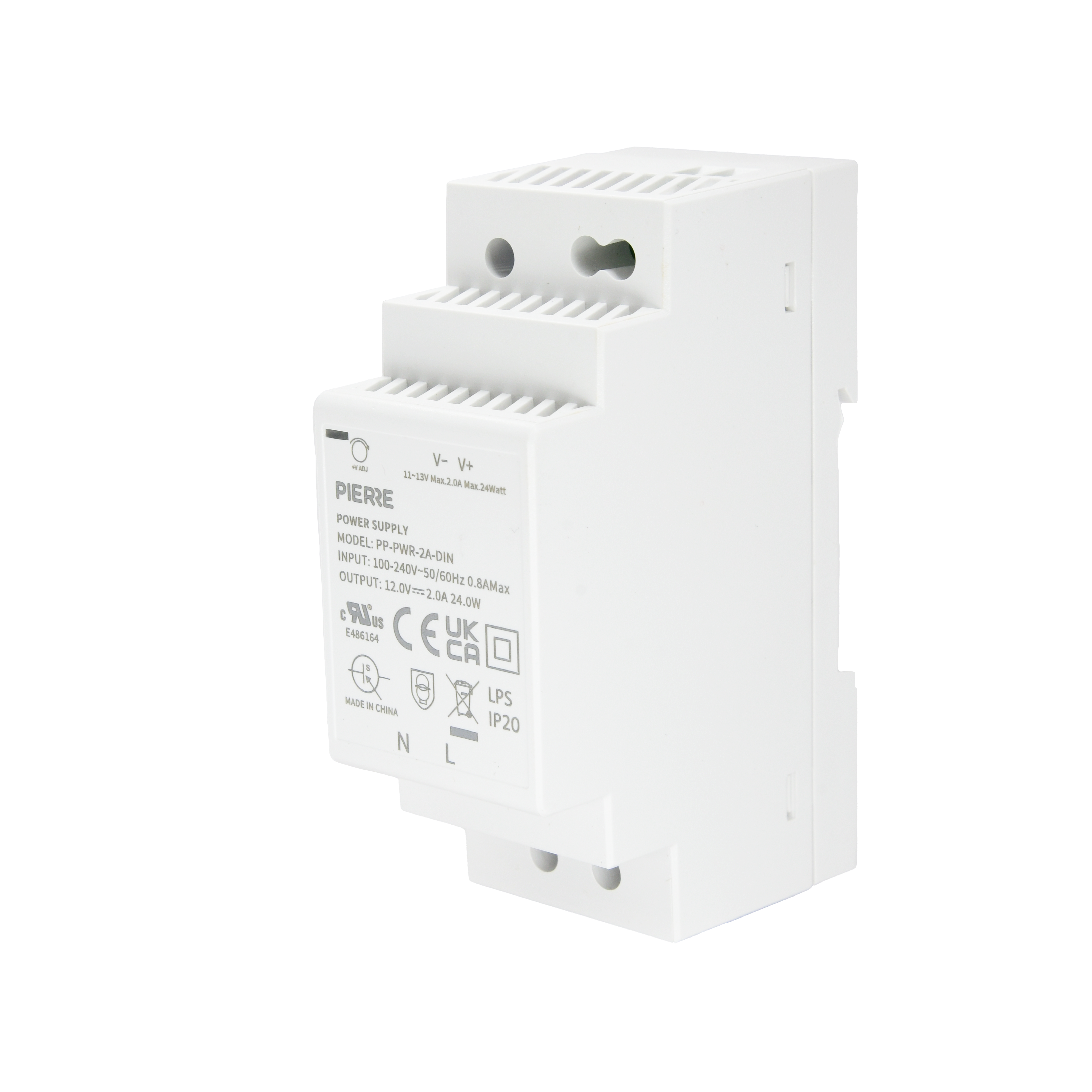
Power Supply 12V/2A (DIN)

SKU: PP-PWR-2A-DIN
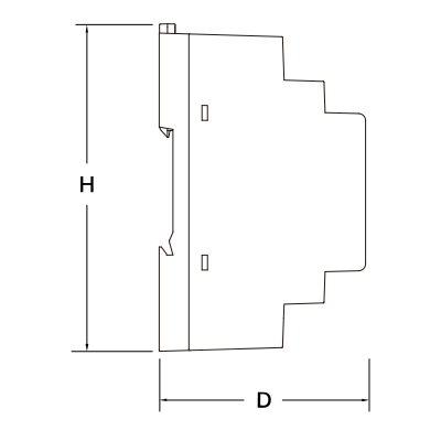
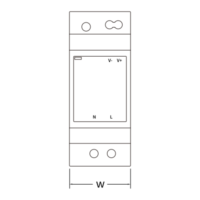
1. Dimensions

Image
  • H: 89 mm
  • D: 59 mm
Image
  • W: 35 mm

2. What you need

Wired. Mains AC input, DIN-rail mounted. Provides 12 V DC for PIERRE devices such as the Controller; size the supply to the total current of everything connected.
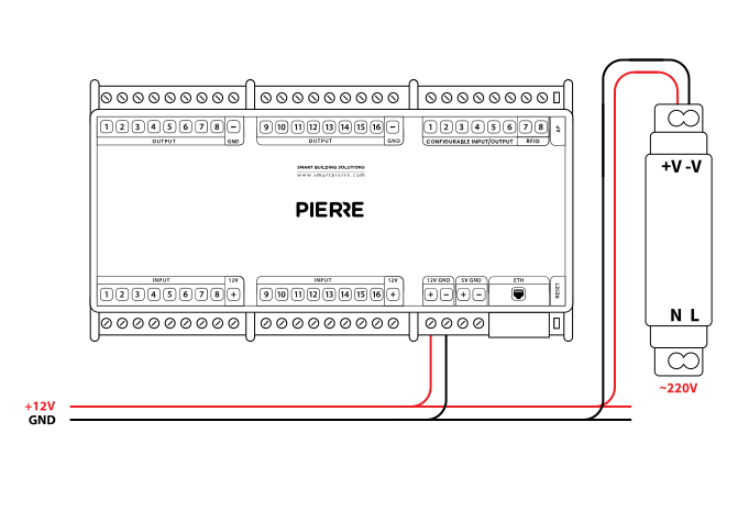
3. Wiring

Image
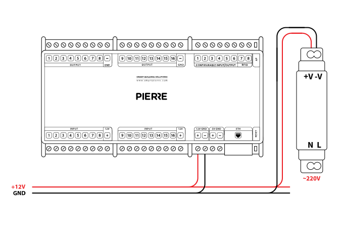
  • Connect the AC input terminals to mains power: L (Live) and N (Neutral).
  • The power supply converts mains AC to 12 V DC; the output terminals are marked V+ and V−.
  • Connect V+ to the 12 V input of the device and V− to its GND.
  • Use the correct conductor cross-section and double-check polarity to avoid damaging connected devices.
Run Wires Cross-section Cable type Conductors
Example: From power supply to Controller 2 0.75 mm² NYM-J +12 V, GND
Image

Example wiring: From Power supply to Controller
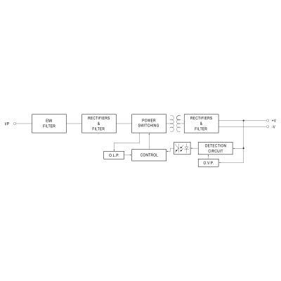
4. Functional Diagram

Image

Functional Diagram – System Overview

The diagram shows the internal stages of a switching mode power supply (SMPS) from AC input to regulated DC output.

Block descriptions:
  • I/P (Input): AC mains voltage is supplied to the power supply.
  • EMI Filter: attenuates conducted and radiated electromagnetic interference and protects downstream components.
  • Rectifiers & Filter (primary side): converts AC to DC and smooths the rectified voltage with capacitive filtering.
  • Power Switching Stage: a high-frequency switching converter (typically a MOSFET) chops the DC voltage to drive the transformer; switching is controlled by PWM (pulse width modulation).
  • Transformer: provides galvanic isolation between input and output and steps the voltage up or down.
  • Rectifiers & Filter (secondary side): converts the high-frequency AC from the transformer back to DC and filters ripple and noise. Delivers the output rails +V and –V.
  • Detection Circuit: monitors the output voltage and generates the feedback for regulation.
  • Control Circuit: processes the feedback and adjusts the switching duty cycle for a stable DC output.
  • O.L.P. (Over Load Protection): detects overload or short circuit on the output and limits the current or shuts the converter down.
  • O.V.P. (Over Voltage Protection): disables the power supply if the output voltage exceeds the set limit.

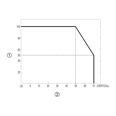
5. Derating Curve

Image
  1. Load (%)
  2. Ambient Temperature (°C)

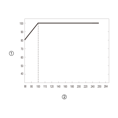
6. Output Derating vs Input Voltage

Image
  1. Load (%)
  2. Input voltage (V AC), 60 Hz