User Manual
Mechanical Relay with Socket (16A 250V AC / 12V DC coil)
SKU: PP-R1-M
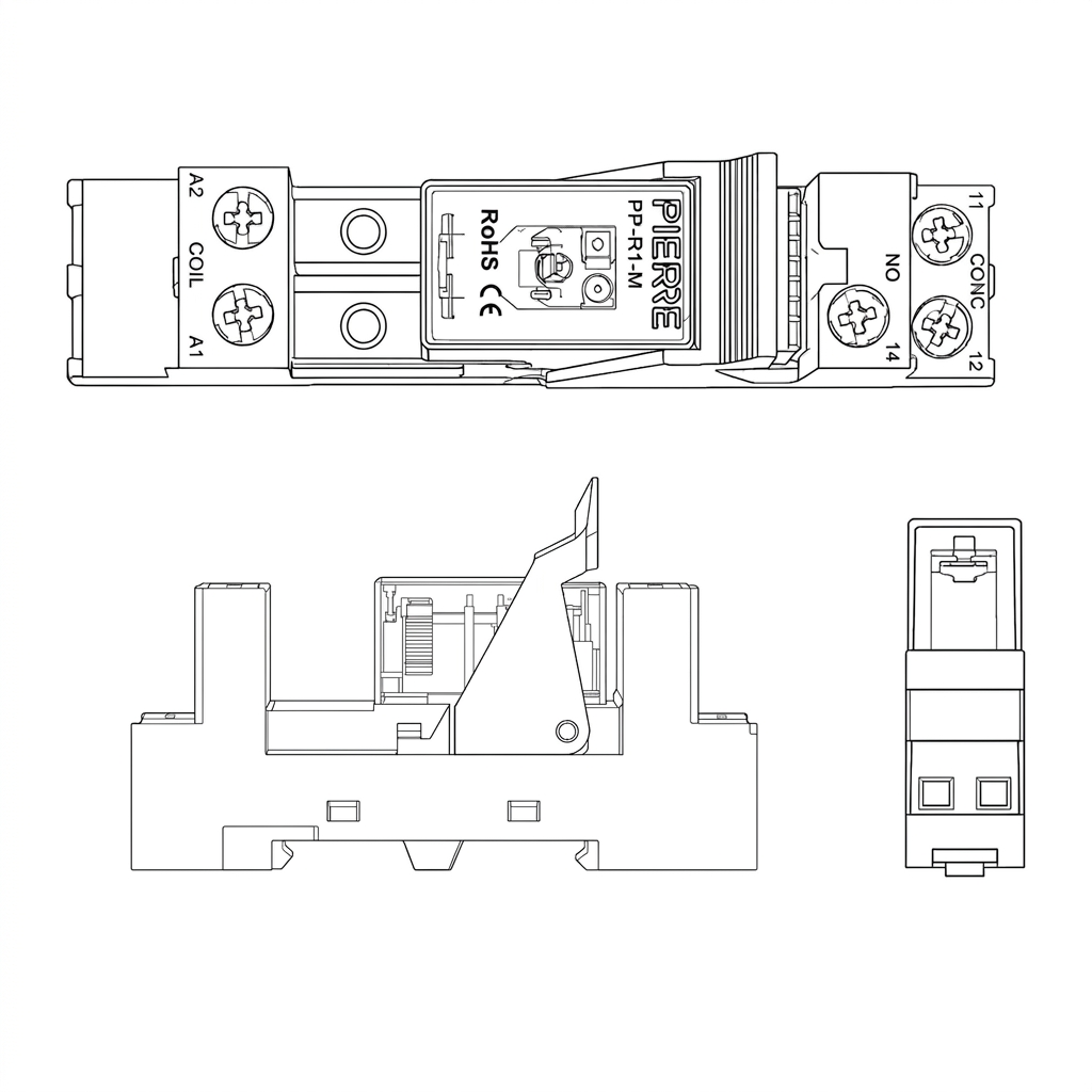
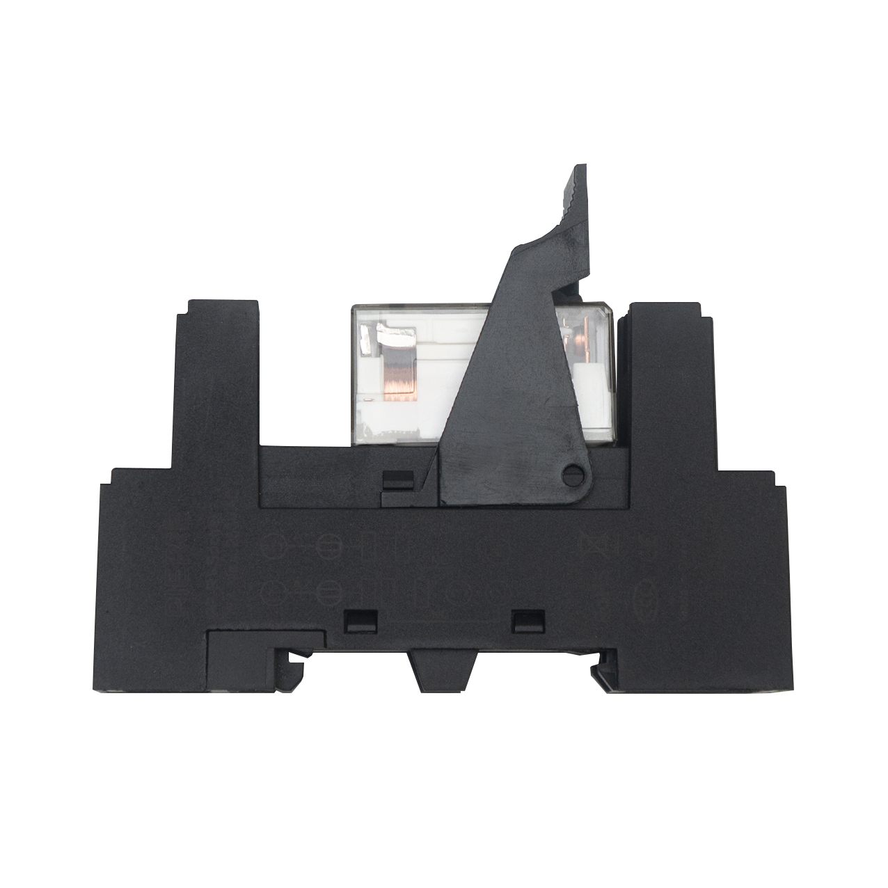
DIN-rail relay module that lets a PIERRE controller switch mains or high-current loads. The coil is driven from a 12 V DC signal output pin on the controller, with a second wire back to the controller's GND to close the circuit. Coil polarity is not critical — A1 and A2 can be interchanged.
The contact side is a potential-free changeover, fully isolated from the 12 V control side:
| Coil Voltage | 12 V DC |
| Contact Rating | 16 A @ 250 V AC (resistive) |
| Contact Material | Silver alloy (Ag alloy) |
| Contact Resistance | ≤100 mΩ |
| Max Switching Power | 4000 VA |
| Max Switching Voltage | 440 V |
| Max Switching Current | 16 A |
| Dielectric Strength | 5000 V AC coil–contact · 1000 V AC contact–contact · 2500 V AC between contact groups · 2000 V AC between adjacent socket terminals (1 min) |
| Surge Voltage | 10 kV (1.2/50 µs), coil to contact |
| Operate Time | ≤15 ms |
| Release Time | ≤8 ms |
| Insulation Resistance (500 V DC) | ≥1000 MΩ |
| Terminal Wire Size | 0.5 – 1 mm² |
| Terminal Screw Torque | 0.8 N·m |
| Relay | 1 changeover contact (SPDT) |
| Operating Temperature | -40 °C to +70 °C |
| Operating Humidity | 35 – 85 % RH |
| Storage Temperature | -40 °C to +55 °C |
| Vibration Resistance | 10–150 Hz, 10 g / 5 g |
| Shock Resistance | Impact 98 m/s², stability 980 m/s² |
| Material | Socket PA6 + GF20 % (RoHS), UL94 V-0; brass terminals, tin-plated |
| Mounting Type | DIN Rail |
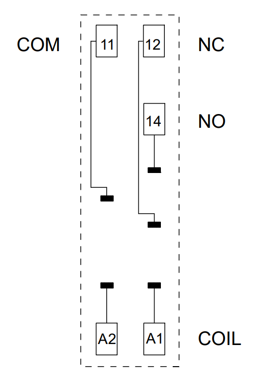
Wire the relay as follows:
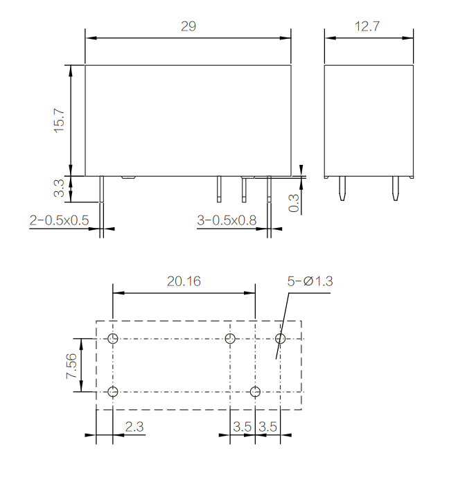
Slim plug-in relay: 29 × 12.7 × 15.7 mm body (3.3 mm pin length below the base).
Five terminals: 2 coil pins 0.5 × 0.5 mm and 3 contact pins 0.5 × 0.8 mm.
PCB footprint: 5 × Ø1.3 mm holes on a 20.16 × 7.56 mm pattern, with 2.3 mm and 2 × 3.5 mm pin spacing along the length.
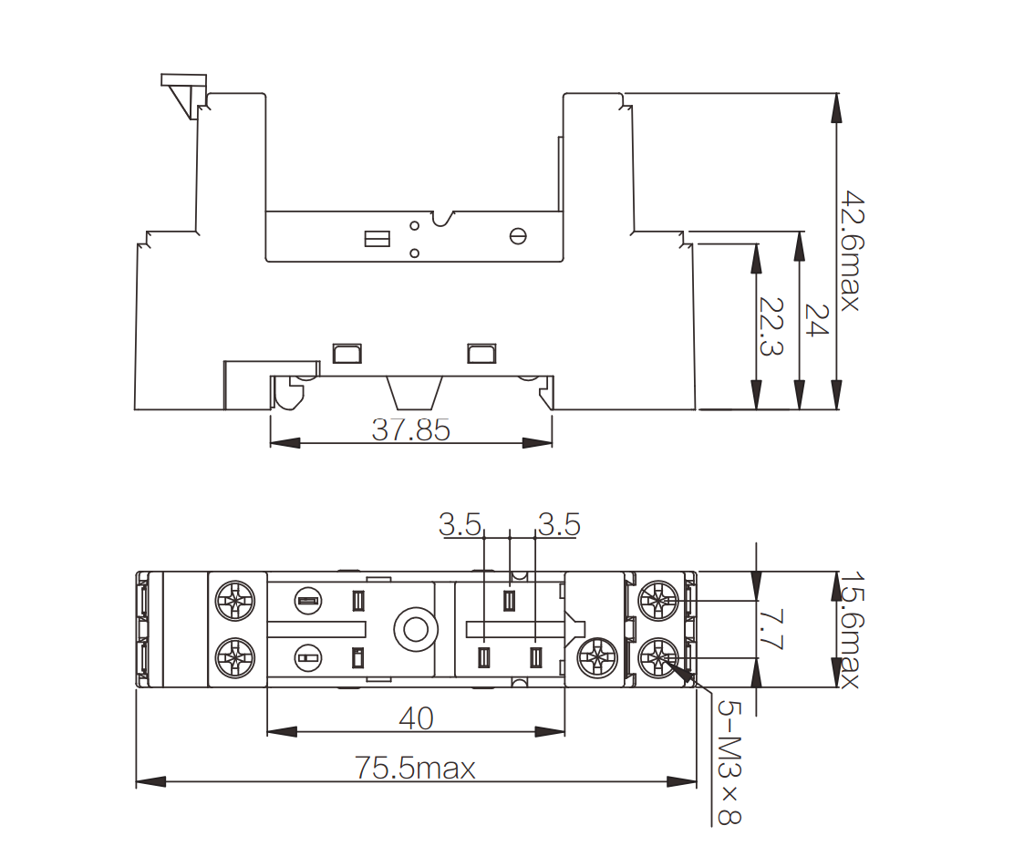
Dimensions: 75.5 × 15.6 × 42.6 mm max, 37.85 mm DIN-rail base width.
Screws: Five M3 × 8 screw terminals; 40 mm terminal span with 2 × 3.5 mm pin spacing.
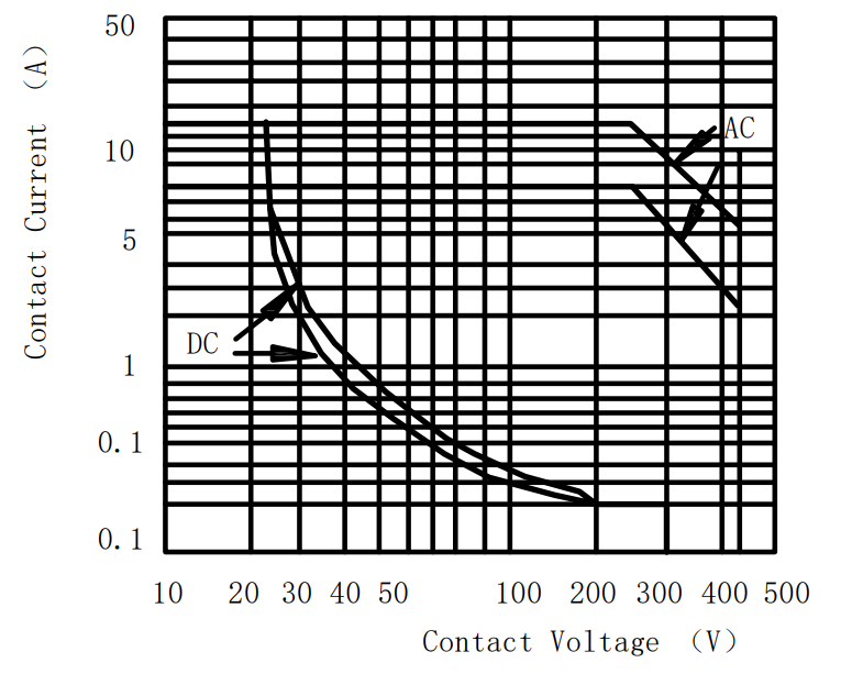
Maximum switching power
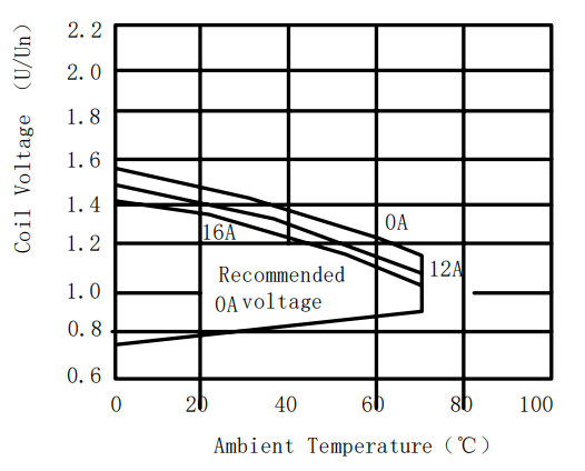
Coil operating temperature curve (AC)
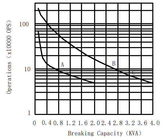
Electrical durability curve