RFID Reader (Keypad + Bell)
User Manual

RFID Reader (Keypad + Bell)

SKU: PP-RFID-CKB

1. Product Description

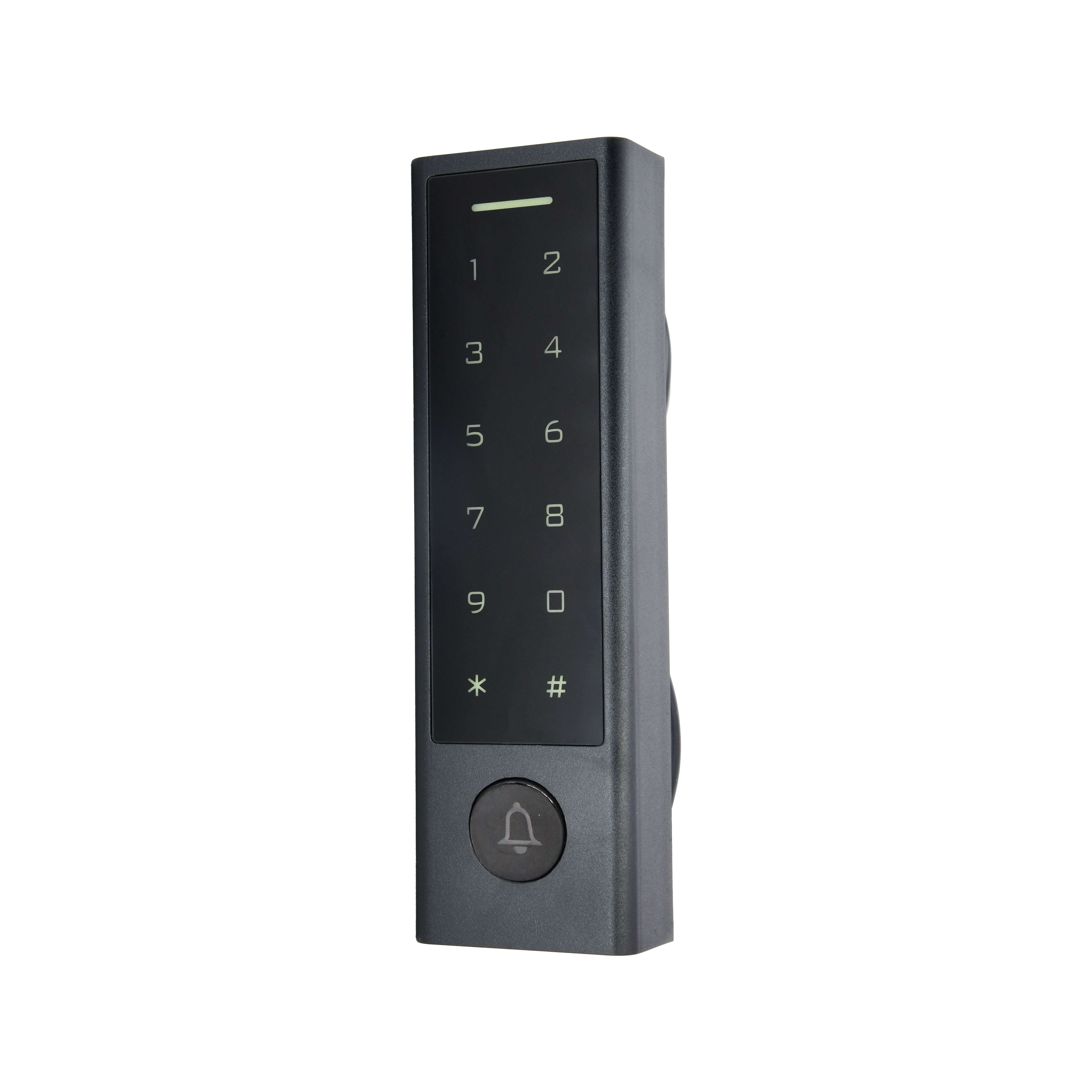
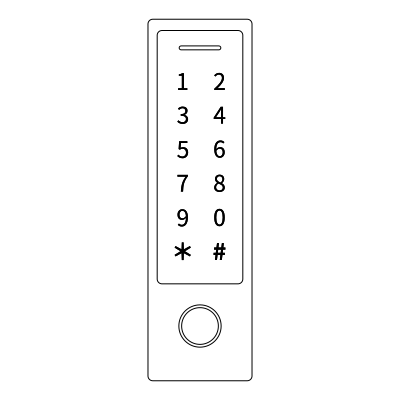
The PIERRE Pro RFID Reader (Keypad + Bell) is a wired access control reader with a PIN keypad, an RFID card reader and a bell button. It connects to a PIERRE PRO or LITE Controller over Wiegand.

The PIERRE Pro RFID reader is available in two versions: Keypad + Fingerprint and Keypad + Bell. This manual covers the Keypad + Bell version.

Control

Access is granted by RFID card or tag, or PIN. The reader uses the Wiegand 34-bit protocol and 13.56 MHz MIFARE cards.

Integration and Management

Set up the reader in the PIERRE Partner app: configure the door, link the reader and create the automation rules. Day-to-day management is done in the Smart PIERRE app: assign roles, define access rights, add or remove users, set PIN codes and register or delete RFID cards.

Bell Button Notification

To receive a notification when the bell button is pressed:

  1. Connect the doorbell ‘B’ wire from the reader to an Input terminal on the PIERRE Controller.
  2. In the PIERRE Partner app add this input as a Button.
  3. When creating the notification, go to the Automation tab and use this Button as a trigger condition (when pressed).

Notifications appear in the Activity tab of the Smart PIERRE app, with the option of a push notification or a phone call.

The reader must be set to Wiegand Reader Mode: * (Master Code) # 7 8 # *.

Note: change the Master Code after installation and configuration (see Changing the Master Code).

Keypad backlight always on: set on the reader with * (Master Code) # 7 5 # *.
2. What's Included

Image
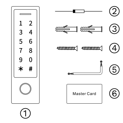
  1. RFID Reader (Keypad + Bell)
  2. Diode 1N4004 (for relay circuit protection)
  3. Wall anchors
  4. Self-tapping screws ϕ 4x25 mm
  5. Screwdriver
  6. Master Card

3. What you need

Wired. Needs a PIERRE PRO or LITE Controller with free configurable I/O pins for the reader (D0 and D1, plus a third pin for LED feedback), plus the RFID reader (Keypad + Bell). The reader takes 12 V from the controller.
4. Installation

Image
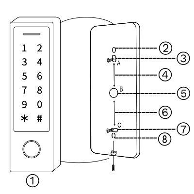
  1. RFID Reader
  2. ϕ 3x3 mm
  3. ϕ 4x6 mm screw hole
  4. 39 mm distance between A and B hole
  5. ϕ 9x9 Cable opening
  6. 39 mm distance between B and C hole
  7. ϕ 3x6 mm screw hole
  8. ϕ 3x3 mm
Installation Steps:
  1. Remove the back cover of the device.
  2. Drill two holes (A, C) on the wall for the screws and one hole (B) for the cable.
  3. Insert the provided rubber plugs into the screw holes (A, C).
  4. Secure the back cover on the wall with 4 flat head screws.
  5. Thread the cables through the cable hole (B).
  6. Attach the main device to the back cover.

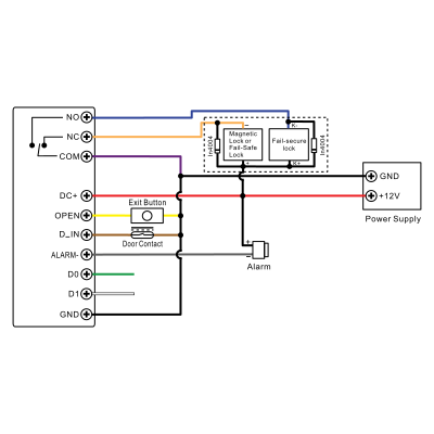
5. Basic Standalone Wiring

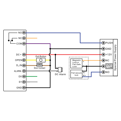
Wire Color and Function Note
Red - DC+ 12–18 V DC power input
Black - GND Negative Pole of the DC Power Input
Blue - Relay NO Normally Open Relay Output (install diode provided)
Purple - Relay Common Common Connection for Relay Output
Orange - Relay NC Normally Closed Relay Output (install diode provided)
Yellow - OPEN Request to Exit (REX) Input

6. Pass-Through Wiring (Wiegand Reader or Controller)

Wire Color and Function Note
Green - Data 0 Wiegand Output (Pass-through) Data 0
White - Data 1 Wiegand Output (Pass-through) Data 1

7. Advanced Input and Output Features

Wire Color and Function Note
Grey - Alarm Output Negative contact for Alarm
Brown - Contact Input Door/Gate Contact Input (Normally Closed)

8. Sound and Light Indication

Operation Status LED and Buzzer
Stand by Red light bright - no buzz
Enter into programming mode Red light flashes - one beep
In programming mode Orange light bright - one beep
Operation error No light indication - just three beeps
Exit from programming mode Red light bright - one beep
Open lock Green light bright - one beep
Alarm Red light flashes quickly - many beeps

9. PIERRE Wiring Diagram

Image

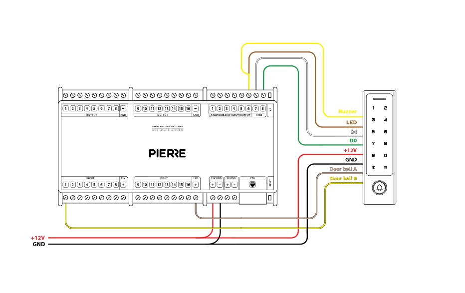
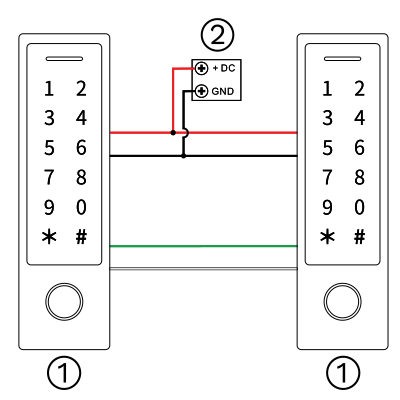
The diagram shows the RFID reader (Keypad + Bell) connected to a PIERRE Controller. A 12 V DC supply feeds both the controller and the reader (Red = +12 V, Black = GND).

Card and PIN data go to the controller over the Wiegand lines D0 (Green) and D1 (White). The LED feedback and buzzer lines give visual and audible feedback on key presses and access validation; in Wiegand Reader Mode (7 8 #) these are the Brown (LED) and Yellow (buzzer) wires.

The bell button is wired to a controller input and added as a Button in the PIERRE Partner app (see Product Description).

Use a common ground between the reader and the controller to keep the Wiegand signal stable.

10. Cable and wiring

Run Wires Cross-section Cable type Conductors
From RFID reader (Keypad + Bell) to PIERRE Controller 7 0.2 mm² (24 AWG) Cat 5e U/UTP +12V, GND, LED, D0, D1, (BUZZ), BELL

11. Basic Configuration

Entering Program Mode

  • Press * followed by the Master Code (Factory default: 123456), then #.
  • The LED will light up to indicate programming mode.
  • To exit Program Mode press *.

12. Changing the Master Code

  • Enter Program Mode with "* Master Code #".
  • To change the Master Code press 0 (New Master Code) # (Repeat New Master Code) #.
  • The Master Code is any 6 digits.

13. Set the Working Mode

The device has 3 working modes:

  1. Standalone Mode
  2. Controller Mode
  3. Wiegand Reader Mode

Choose the mode you want to use:

  • Enter Program Mode (* Master Code #)
  • For Standalone/Controller Mode press 7 7 # (Factory default)
  • For Wiegand Reader Mode press 7 8 #
  • To exit press *

14. STANDALONE MODE

The device can work as Standalone Access Control for a single door. Factory default mode - 7 7 #

Attention: Install a 1N4004 or equivalent diode when using a common power supply, or the reader might be damaged. (1N4004 is included in the packaging.)
15. Common Power Supply

Image

16. Access Control Power Supply

Image

17. Programming

The programming process will vary based on the access configuration. Ensure you follow the instructions specific to your chosen configuration.

  • User ID number: Assign a user ID to each card or PIN in order to track it.
    • PIN/Card user ID: 100 – 987
    • Panic user ID: 988 – 989
    • Visitor user ID: 990 – 999

Note: User IDs do not require leading zeros. It is crucial to record the User ID accurately. Any modifications to the user will require the original User ID.

  • Proximity Card: EM card or EM + Mifare cards
  • PIN: Can be any 4–6 digits, except 8888 which is reserved.

18. Add Card User

  1. Enter Programming Mode: press *, followed by the Master Code, and then #.
  2. Adding a Card User (user ID 100–987). There are three methods:
    1. Using Auto ID: enter 1, then either swipe the card on the reader or input the 8, 10 or 17-digit card number, and press #. Cards can be added continuously.
    2. Assigning a specific User ID: enter 1 (User ID) #, then swipe the card or input the 8, 10 or 17-digit card number, and press #.
    3. Block enrollment (up to 888 cards in one step, takes about 2 minutes): enter 1 (User ID) # (Card Quantity) # (first card 8, 10 or 17-digit number) #.
  3. Exit Programming Mode: press *.

Important Notes:

  • For block enrollment the card numbers must be consecutive.
  • Card Quantity is the total number of cards enrolled in the batch.

19. Add PIN User

  1. Enter Programming Mode: press *, followed by the Master Code, and then #.
  2. Adding a PIN User (user ID 100–987). There are two methods:
    1. Using Auto ID: enter 1 (PIN) #. PINs can be added continuously.
    2. Assigning a specific User ID: enter 1 (User ID) # (PIN) #.
  3. Exit Programming Mode: press *.

Important Notes:

  • PINs can be 4 to 6 digits long, except 8888 which is reserved.
  • Keep a record of assigned User IDs to prevent duplication or confusion.

20. Add Panic User

Panic User IDs are 988 and 989 (valid for card and PIN users).

  1. Enter Programming Mode: press *, followed by the Master Code, and then #.
  2. Add a Panic User:
    1. Card User: enter 1 (988 or 989) #, swipe the card or input the 8, 10 or 17-digit card number, then #.
    2. PIN User: enter 1 (988 or 989) # (PIN) #.
  3. Exit Programming Mode: press *.

Important Notes:

  • Panic users are configured for emergency access scenarios.
  • Reserve these IDs for authorized personnel only, as they may trigger emergency features.

21. Add Visitor Users

Visitor User IDs are reserved as 990 to 999 (valid for card and PIN users). There are 10 visitor groups, each usable a set number of times; after that number of uses the card or PIN becomes invalid automatically.

  1. Enter Programming Mode: press *, followed by the Master Code, and then #.
  2. Add a Visitor User:
    1. Card User: enter 1 (990–999) # (0–9) #, swipe the card or input the 8, 10 or 17-digit card number, then #.
    2. PIN User: enter 1 (990–999) # (0–9) # (PIN) #.
    0–9 is the number of times the visitor credential can be used; 0 means 10 times.
  3. Exit Programming Mode: press *.

Important Notes:

  • Visitor users are for temporary or guest access.
  • Monitor visitor IDs and deactivate them when no longer needed.

22. Change User PIN

The following actions are performed outside of programming mode and can be completed by users independently.

  • To change the PIN of an existing user: enter * (User ID) # (Old PIN) # (New PIN) # (New PIN) #.
  • To change the PIN of a card (cards are given the PIN 8888 automatically when added): enter *, read the card, then (Old PIN) # (New PIN) # (New PIN) #.

Important Notes:

  • The PIN must be 4 to 6 digits long.
  • Avoid using the reserved PIN 8888.
  • Always keep a record of User IDs and PINs.

23. Delete Users

  1. Enter Programming Mode: press *, followed by the Master Code, and then #.
  2. Delete a user by card or PIN: enter 2, then read the card or input the PIN, then #. Users can be deleted continuously.
  3. Delete a user by User ID: enter 2 (User ID) #.
  4. Delete a user by card number: enter 2 (8, 10 or 17-digit card number) #.
  5. Delete all users: enter 2 (Master Code) #.
  6. Exit Programming Mode: press *.

Important Notes:

  • Always record and verify User IDs or card numbers before deletion.
  • Deleting all users cannot be undone.

24. Set Relay Configuration

The relay configuration determines the behavior of the output relay during activation.

  1. Enter Programming Mode: press *, followed by the Master Code, and then #.
  2. Pulse Mode: enter 3 (1–99) #. The relay time is 1–99 seconds (factory default 5 seconds). Example: 3 5 # for 5 seconds.
  3. Toggle Mode: enter 3 0 #. The relay stays switched until the next valid credential.
  4. Exit Programming Mode: press *.

Important Notes:

  • Toggle mode is used for continuous access; pulse mode is used for momentary door unlocking.

25. Set Access Mode

For multi-user access mode, the interval between reads cannot exceed 5 seconds, otherwise the device returns to standby automatically.

  1. Enter Programming Mode: press *, followed by the Master Code, and then #.
  2. Set the access mode:
    1. Card access: enter 4 1 #.
    2. PIN access: enter 4 2 #.
    3. Card + PIN access: enter 4 3 #.
    4. Multi-user access: enter 4 3 (2–9) #. The door opens only after 2–9 valid users have presented their credentials.
  3. Exit Programming Mode: press *.

26. Set Strike-out Alarm

The strike-out alarm activates after 10 failed entry attempts. By default it is OFF. It can be configured to deny access for 10 minutes, or to disengage only after a valid card, PIN or Master credential.

  1. Enter Programming Mode: press *, followed by the Master Code, and then #.
  2. Configure the strike-out alarm:
    1. Strike-Out OFF: enter 6 0 # (factory default).
    2. Strike-Out ON: enter 6 1 #. Access is denied for 10 minutes; the exit button still works.
    3. Strike-Out ON with alarm: enter 6 2 #.
  3. Set Alarm Time: enter 5 (0–3) #. Factory default is 1 minute.
  4. To silence the alarm: enter the Master Code #, use the Master Card, or a valid user card or PIN.
  5. Exit Programming Mode: press *.

27. Set Door Open Detections

Door Open Too Long (DOTL) Detection
  • When used with an optional magnetic contact or the built-in magnetic contact of the lock: if the door is opened normally but not closed within 1 minute, the inside buzzer beeps automatically to remind people to close the door.
  • The beep stops by closing the door or by a Master User or valid user credential; otherwise it continues for the alarm time set.
Door Forced Open Detection
  • If the door is opened by force, the inside buzzer and the external alarm (if fitted) both activate.
  • They are stopped by Master Users or valid users; otherwise they continue for the alarm time set.
Programming Steps
  1. Enter Programming Mode: press *, followed by the Master Code, and then #.
  2. Disable Door Open Detection: enter 6 3 # (factory default).
  3. Enable Door Open Detection: enter 6 4 #.
  4. Set Alarm Time: enter 5 (0–3) #. Factory default is 1 minute.
  5. Exit Programming Mode: press *.

Additional Note: the Set Alarm Time function also applies to the anti-tamper alarm.

28. Set Audible and Visual Response

  1. Enter Programming Mode: press *, followed by the Master Code, and then #.
  2. Sound: Disable sound 7 0 #; Enable sound 7 1 # (factory default).
  3. LED: LED always OFF 7 2 #; LED always ON 7 3 # (factory default).
  4. Keypad backlight: always OFF 7 4 #; always ON 7 5 #; automatic OFF 7 6 # (factory default).
  5. Exit Programming Mode: press *.

Note: in automatic mode the keypad backlight turns off after 20 seconds. It turns on again by pressing any key (that key press is not registered).

29. Using Master Card to add and delete users

Add Card or PIN Users:

  1. Present the Master Card.
  2. Add the user by one of the following methods: swipe the card, or input the PIN followed by #.
  3. Repeat step 2 for additional users.
  4. Finish by presenting the Master Card again to save and exit.

Delete Card or PIN Users:

  1. Present the Master Card twice within 5 seconds.
  2. Delete the user by one of the following methods: swipe the card, or input the PIN followed by #.
  3. Repeat step 2 for additional users.
  4. Finish by presenting the Master Card again to save and exit.

30. Users Operation & Reset to Factory Default

  • Open the Door: read a valid user card, or input a valid user PIN followed by #.
  • Remove Alarm: enter the Master Code followed by #, use the Master Card, or a valid user card or PIN.

To Reset to Factory Default and add a Master Card:

  1. Power off the device.
  2. Press and hold the Exit Button while powering the device back on. You will hear two beeps.
  3. Release the Exit Button. The LED turns yellow.
  4. Present any 125 kHz EM card or 13.56 MHz Mifare card. The LED turns red, indicating a successful reset to factory default. The card used becomes the Master Card.

Additional Notes:

  • If no Master Card is to be added, press the Exit Button for at least 5 seconds before releasing it. This invalidates any previously registered Master Card.
  • Resetting to factory default retains the user information.

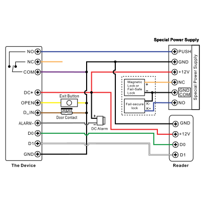
31. CONTROLLER MODE

The device can function as a controller when connected to an external Wiegand reader.

Factory default mode: enter 7 7 #

Attention: install a 1N4004 diode (or equivalent) when using a common power supply to prevent damage to the reader. A 1N4004 diode is included in the package.
32. Connection Diagram

Image

33. Set Wiegand Input Formats

Configure the Wiegand input formats to match the output format of the external reader.

  1. Enter Programming Mode: press *, followed by the Master Code, and then #.
  2. Set the Wiegand input bits:
    1. For EM cards: enter 8 (26–44) # (factory default is 26 bits).
    2. For Mifare cards: enter 8 0 (26–44, 56, 58) # (factory default is 34 bits).
  3. Parity bit: disable 8 0 #; enable 8 1 # (factory default).
  4. Exit Programming Mode: press *.

Note: when connecting Wiegand readers with 32, 40 or 56-bit output, parity bits must be disabled.

34. Programming in Controller Mode

  • Basic programming is the same as in Standalone Mode.
  • Device connected with an external card reader:
    • EM/Mifare card readers: users can be added or deleted on either the device or the external reader.
    • HID card readers: users can only be added or deleted on the external reader.

35. Device Connected with Keypad Reader

The keypad reader supports 4-bit, 8-bit (ASCII) or 10-bit output formats. Choose the setting that matches the PIN output format of your reader.

  1. Enter Programming Mode: press *, followed by the Master Code, and then #.
  2. Set PIN input bits: enter 8 (4 or 8 or 10) # (factory default is 4 bits).
  3. Exit Programming Mode: press *.

Remarks: 4 means 4 bits, 8 means 8 bits, 10 means a 10-digit virtual number.

Add PIN users: after entering programming mode, PINs can be added on either the device or the external keypad reader. Delete PIN users: the same way as adding users.

36. WIEGAND READER MODE

The device can function as a standard Wiegand reader connected to a third-party controller.

Activate Wiegand Reader Mode: enter 7 8 #

Notes:
  • In Wiegand Reader Mode nearly all Controller Mode settings become invalid, and the Brown and Yellow wires are redefined: Brown wire controls the green LED, Yellow wire controls the buzzer.
  • When the input voltage on the LED wire is low the LED turns green; when the input voltage on the buzzer wire is low the buzzer sounds.

37. Connection Diagram

Image

38. Set Wiegand Output Formats

Configure the Wiegand output formats of the reader to match the input formats of the controller.

  1. Enter Programming Mode: press *, followed by the Master Code, and then #.
  2. Set the Wiegand output bits:
    1. For EM cards: enter 8 (26–44) # (factory default is 26 bits).
    2. For Mifare cards: enter 8 0 (26–44, 56, 58) # (factory default is 34 bits).
    3. PIN output bits: enter 8 (4 or 8 or 10) # (factory default is 4 bits).
  3. Parity bit: disable 8 0 #; enable 8 1 # (factory default).
  4. Exit Programming Mode: press *.

Note: when connecting to Wiegand controllers with 32, 40 or 56-bit input, parity bits must be disabled.

39. ADVANCED APPLICATION

Collection Card Mode

When this mode is activated, all cards can open the lock and each card is added to the device at the same time.

  1. Enter Programming Mode: press *, followed by the Master Code, and then #.
  2. Collection Card Mode OFF: enter 9 2 # (factory default). Collection Card Mode ON: enter 9 3 #.
  3. Exit Programming Mode: press *.

User Information Transfer (valid for card and PIN users)

This feature transfers the enrolled card and PIN users from one device (the Master Unit) to another (the Accept Unit).
  • The Master Unit and Accept Unit must be devices of the same series.
  • The Master Code of both units must be identical.
  • Perform the transfer operation on the Master Unit only.
  • Users already enrolled on the Accept Unit are overwritten.
  • Transferring the maximum of 900 users takes about 30 seconds.

40. Connection Diagram

Image

41. Set Transferring on Master Unit

  1. Enter Programming Mode: press *, followed by the Master Code, and then #.
  2. Initiate transferring: enter 9 8 #. Within 30 seconds the green LED shines; after one beep the LED turns red, indicating the user information has been transferred successfully.
  3. Exit Programming Mode: press *.

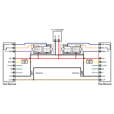
42. Interlock

The device supports the Interlock Function, which is designed for managing two devices controlling two doors. It is primarily used in banks, prisons, and other locations requiring a higher level of security.
43. Connection Diagram

Image

44. Interlock Setup and Configuration

A door contact must be installed and connected on each door as shown in the diagram. Name the two devices “A” and “B” for doors “1” and “2”.

Step 1: Enroll users on Device A, then transfer the card and PIN users to Device B with the User Information Transfer function.

Step 2: Set both devices to Interlock:

  1. Enter Programming Mode: press *, followed by the Master Code, and then #.
  2. Disable Interlock: enter 9 0 # (factory default). Enable Interlock: enter 9 1 #.
  3. Exit Programming Mode: press *.

With interlock enabled: only when Door 2 is closed can a valid card or PIN on Reader A open Door 1; only when Door 1 is closed can a valid card or PIN on Reader B open Door 2.

45. FAQ

Q1: How many readers can I add to one PIERRE Controller?

On one PIERRE Controller you can add 2 RFID readers with LED feedback. If you do not need feedback, you can add 4 RFID readers. Two readers can be connected in parallel on the same configurable I/O pins if they both open the same door.

Q2: Can I get a notification with a traditional doorbell?

If the doorbell is not connected to the PIERRE system, you will not receive a notification. A traditional doorbell can be connected to a PIERRE Controller input, added as a Button in the PIERRE Partner app and used as a trigger for a notification.