User Manual
Flood sensor
SKU: PP-SNS-FS
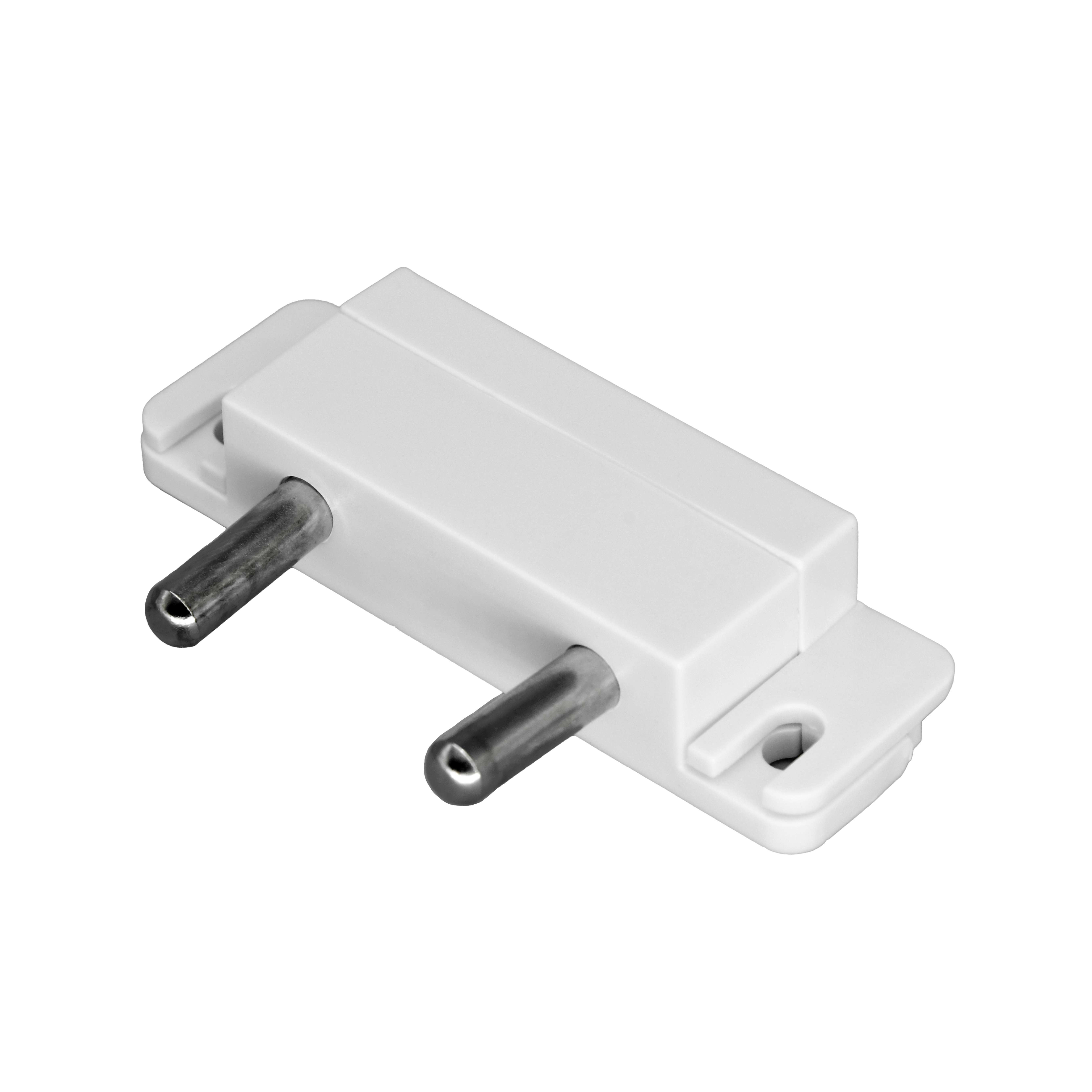
The PIERRE Pro Flood Sensor detects standing water and reports it to the controller. IP67, for floor or low wall mounting in plant rooms, bathrooms and basements.
The PIERRE leak sensor detects water or excessive moisture at a specific point and reports it to the system. It is housed in a compact casing and detects water by conductivity or capacitance between its contacts.
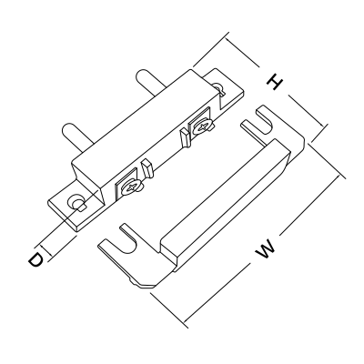
Wired. Needs a PIERRE PRO or LITE Controller with a free input, plus the Flood sensor. The sensor takes 12 V from the controller.
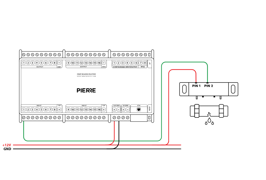
| Run | Wires | Cross-section | Cable type | Conductors |
|---|---|---|---|---|
| From Flood sensor to PIERRE Controller | 2 | 0.2 mm² (24 AWG) | Cat 5e U/UTP | +12 V, SIGNAL |
Check two things physically: whether the polarity is reversed, and whether the sensor is permanently reporting a flood because its contacts are wet or bridged.
Green – online and connected. Red – offline, no network or no internet. Light blue – AP mode, broadcasting its own network for setup. Dark blue – AP mode managed through PIERRE Partner. Purple – searching for an IP address from the router. Orange – downloading a firmware update.
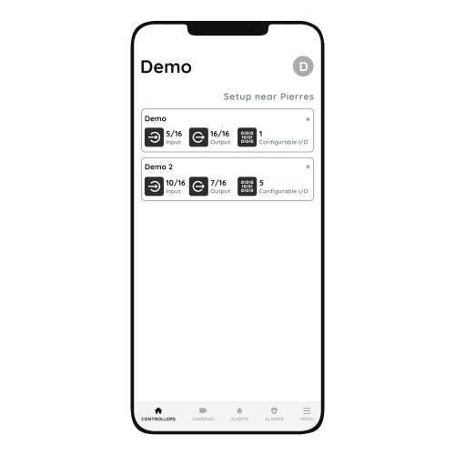
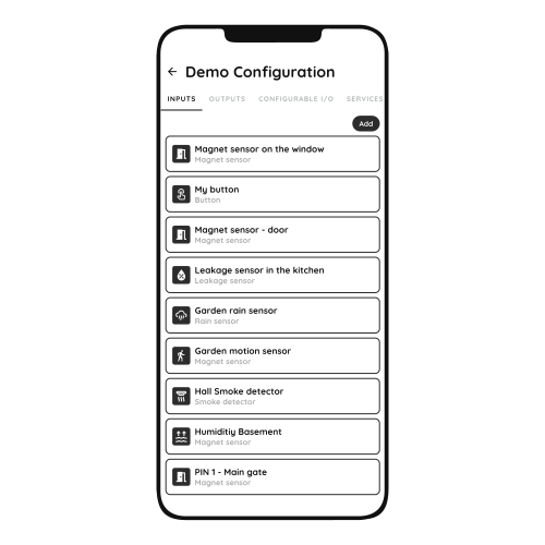
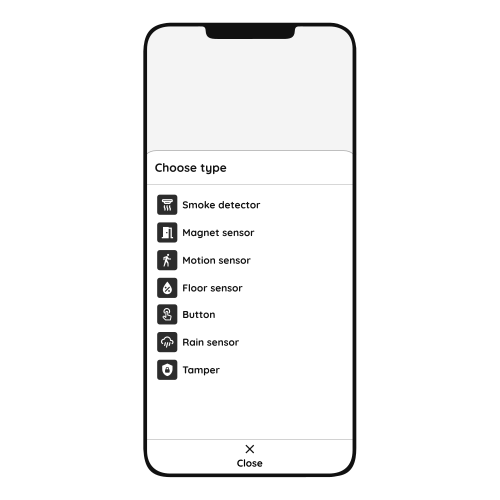
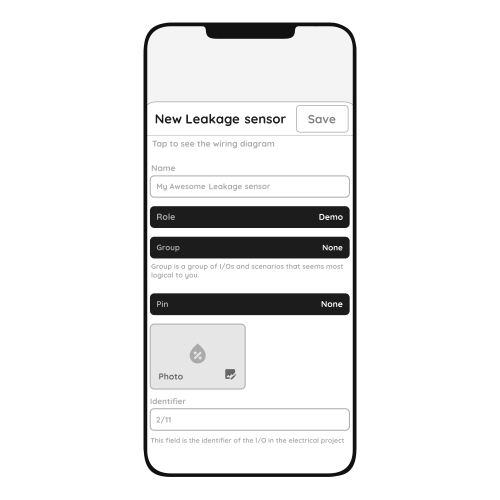
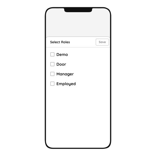
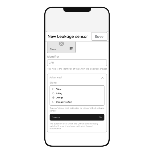
Check that the sensor has been added to the configuration in the PIERRE Partner application.
A newly added sensor needs a state change before it reports. Wet the contacts once, then dry them.
It must be connected to 12 V and a PIERRE input as shown in the wiring diagram. To find out whether the fault is in the sensor or in the cable, briefly bridge 12 V to the PIERRE input the sensor uses. If the dot turns green in the app, the fault is the sensor or a broken wire.
If one input influences an output, both should be added to the same controller. A motion sensor triggering a lamp, for example, performs best when both sit on the same controller.
Near water sources — under sinks, next to the washing machine and dishwasher, at the water heater, boiler and manifold — with the contacts on the floor at the lowest point where water would collect.
Each sensor is wired individually back to the PIERRE cabinet in a star pattern. INPUT 12–24 V takes 12 V DC from the controller, GND takes ground from the controller, switch terminal K1 (IN) is bridged to INPUT 12–24 V, and switch terminal K2 (OUT) goes to the input on the controller.