Magnetic contact sensor
User Manual

Magnetic contact sensor

SKU: PP-SNS-MCS

1. Product Description

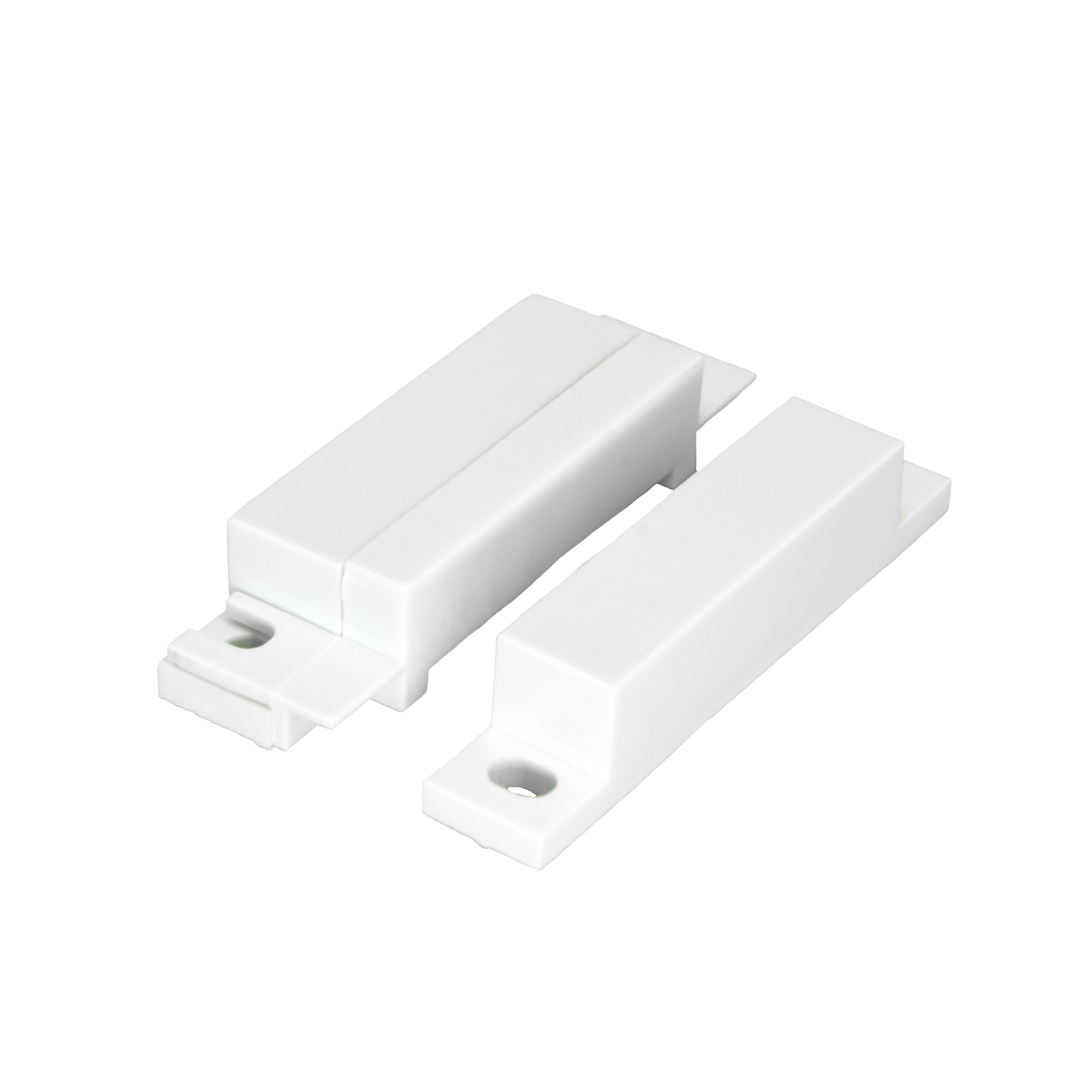
The PIERRE Pro Magnetic Contact Sensor is the wired door and window contact of the PIERRE Pro system.

The PIERRE wired contact sensor reports whether a door or window is open or closed. It has two parts — a sensor unit and a magnet — and detects the state from the magnetic field between them.

Installation

  • The sensor is fitted into the door or window frame and the magnet on the opening part, so both are concealed when the opening is closed.
  • The sensor is wired back to a controller input; there is no battery to replace.
  • It is configured in the PIERRE Partner application, and then appears in the Smart PIERRE application.

Wired or Wireless

The wired sensor keeps a continuous connection to the controller and never needs a battery, which makes it the better choice where the frame is accessible during the first fix. Where cabling is not possible, the wireless version provides the same function.
Use in Automations

  • Reduce or switch off heating and cooling while a window is open.
  • Switch on lighting when a door is opened.
  • Send an alert when an opening changes state while the property should be empty.
  • Trigger an alarm or external lighting as part of a security function.

Technical Notes

  • Recessed sensors have to be planned before the frame is fitted. Adding one afterwards means working on a finished frame.
  • Keep the magnet gap within specification. On a door that settles over time the gap grows and the sensor starts reporting open.
  • Check the sensor's rest state before configuring; a normally-closed sensor reports the opposite of a normally-open one.
  • Test every sensor physically at handover, opening and closing the actual door or window.

2. Dimensions

Image
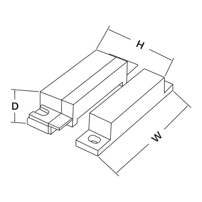
  • D: 13 mm
  • H: 12 mm
  • W: 62 mm

3. What you need

Wired. Needs a PIERRE PRO or LITE Controller with a free input, plus the Magnetic contact sensor. The sensor takes 12 V from the controller.
4. Wiring

Image
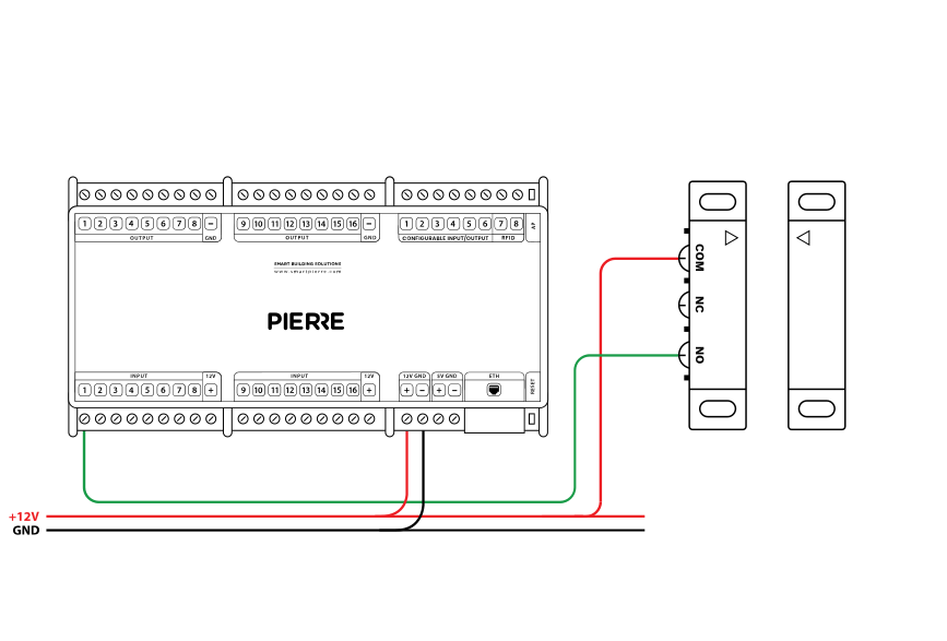
  1. Connect the COM terminal of the sensor to +12 V on the controller.
  2. Connect the NO (normally open) terminal to a PIERRE input on the controller (e.g. IN1).
Run Wires Cross-section Cable type Conductors
From Contact sensor to PIERRE Controller 2 0.2 mm² (24 AWG) Cat 5e U/UTP +12 V, INPUT

5. Magnetic contact sensor setup via App

Image
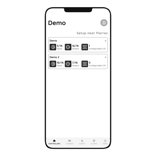
  1. Choose Controller
    1. Tap on the Controller that you would like to add new I/O to.
    2. To edit the I/O, click on the Controller to which the I/O is added.
Image
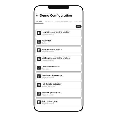
  1. Add button for Inputs
    1. Inputs tab is selected.
    2. List of Inputs is shown.
    3. In order to add new Input tap on the Add button.
Image
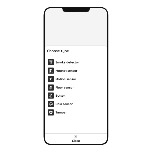
  1. Choose type - Inputs
    1. From the list that is shown tap on the desired I/O that you would like to add.
Image
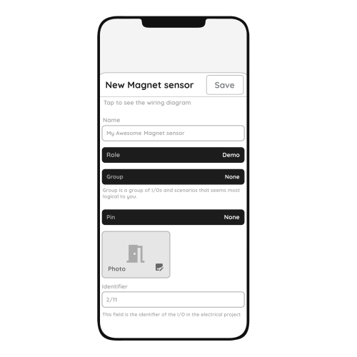
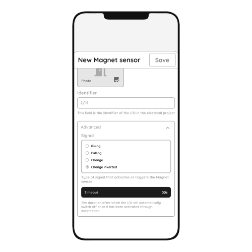
  1. New Magnet Contact sensor
    1. Fill the following form:
    2. Name - Write the name of the Magnet sensor.
      1. Role - Choose Role from the list.
      2. Group - Choose Group from the list. Group is a group of I/O and scenarios that seems most logical to you.
      3. Pin - Choose Pin from the list. Pin is physical place on the Controller where I/O is connected to it.
      4. Photo - Choose photo for the Magnet sensor.
      5. Identifier - This field is the identifier of the I/O in the electrical project.
      6. Advanced - You can choose type of the signal that activates or triggers the Magnet sensor: rising, falling, change, change inverted.
      7. Timeout - It is the duration for which the Magnet Contact  sensor will remain Open in auto mode.
    3. When you want to confirm your choice tap Save and Submit.
Image
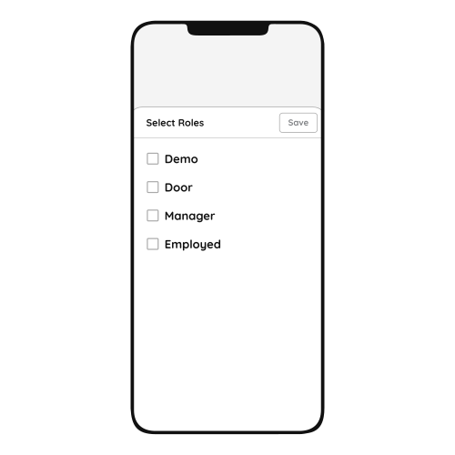
  1. Select Roles - Inputs
    1. Tap in the field Roles.
    2. Select checkbox/checkboxes (for multiple choice) next to the Role/Roles that you would like to choose.
    3. To confirm selection tap the button Save/Done.
Image
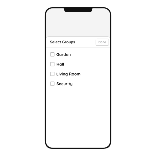
  1. Select Groups - Inputs
    1. In this step you should select Group.
    2. Select check box/check boxes next to the desired Group/Groups from the list.
    3. When you want to confirm your choice tap button Done/Save.
Image
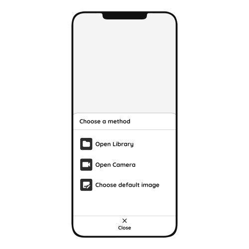
  1. Change Photo
    1. Tap on the photo of the Magnet Contact  sensor.
    2. You have three options:
      1. Open Library - The phone’s Library will open.
      2. Open Camera - You can take a picture using your smartphone.
      3. Choose default image - Use one of the prepared images.
Image
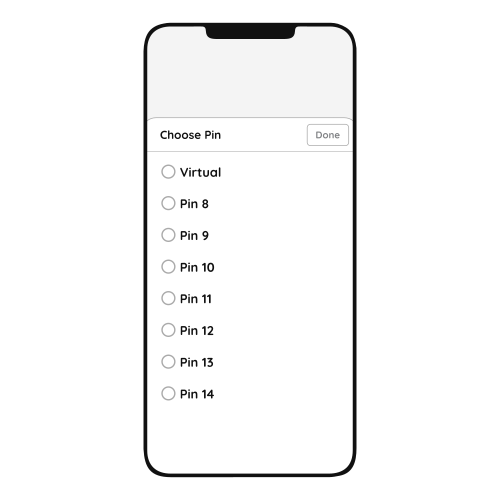
  1. Choose Pin
    1. Tap on the radio button next to the Pin that you would like to choose.
    2. To confirm selection tap on Save/Done.
Image
  1. Advanced - Magnet Contact sensor
    1. Tap radio button next to the type of signal that you would like to choose.
    2. You can choose:
      1. Rising
      2. Falling
      3. Change
      4. Change inverted
    3. You can choose type of the signal that activates or triggers the Magnet Contact sensor.

6. FAQ

Q1: The sensor does not react in the app. What should I check first?

Check that the sensor has been added to the configuration in the PIERRE Partner application.

Q2: The sensor was just added and shows no state. Why?

A newly added sensor needs a state change before it reports. Open and close the door or window once.

Q3: How do I check that the sensor is wired correctly?

It must be connected to 12 V and a PIERRE input as shown in the wiring diagram. To find out whether the fault is in the sensor or in the cable, briefly bridge 12 V to the PIERRE input the sensor uses. If the dot turns green in the app, the fault is the sensor or a broken wire.

Q4: When should input and output be on the same controller?

If one input influences an output, both should be added to the same controller. A motion sensor triggering a lamp, for example, performs best when both sit on the same controller.

Q5: When should contact sensors be installed?

PIERRE Pro contact sensors are installed during construction, because they need wiring in the frame or wall. PIERRE Wave contact sensors are wireless and can be added later.

Q6: Where should the contact sensor be placed?

Sensor and magnet must be aligned when the door or window is closed. On windows, placing the sensor at the top lets it detect a tilted window as open.

Q7: How should the sensors be wired?

Each sensor is wired individually back to the PIERRE cabinet in a star pattern. INPUT 12–24 V takes 12 V DC from the controller, GND takes ground from the controller, switch terminal K1 (IN) is bridged to INPUT 12–24 V, and switch terminal K2 (OUT) goes to the input on the controller.