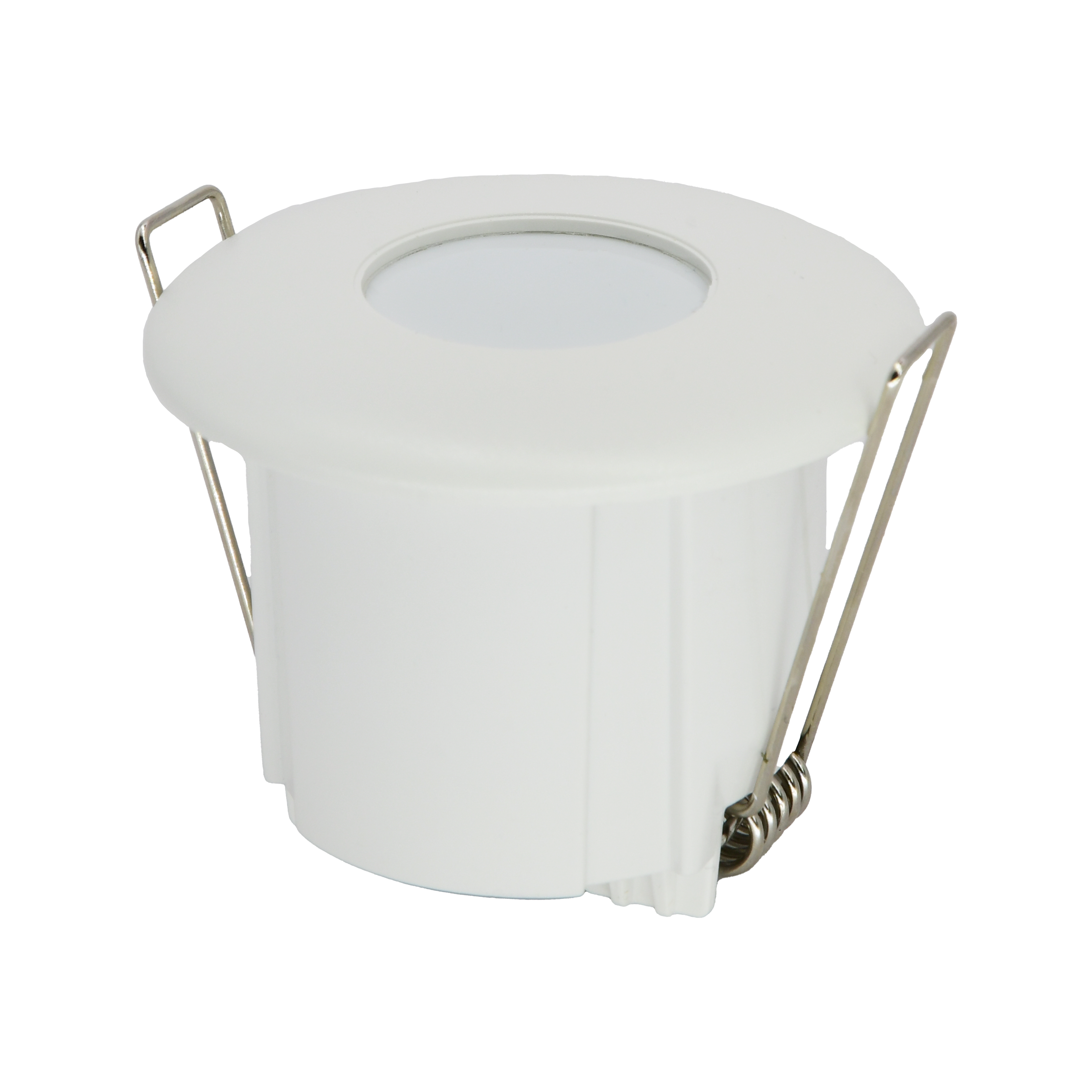
Motion Sensor 360 (Flush Mount)
User Manual

Motion Sensor 360 (Flush Mount)

SKU: PP-SNS-MOTION-F
1. Dimensions

Image
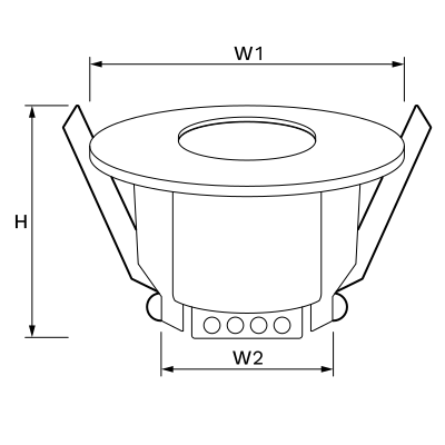
  • H: 39 mm
  • W1: 52 mm
  • W2: 40 mm
Image

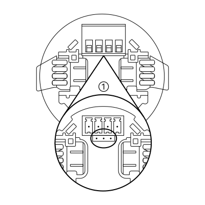
A jumper behind the output terminal selects normally open or normally closed operation. Default: normally open.

Normally open: the relay closes (signal present) when someone is detected and opens (no signal) when the area is empty.

Normally closed: the relay closes (signal present) when the area is empty and opens (no signal) when someone is detected.

2. What you need

Wired. Needs a PIERRE PRO or LITE Controller with a free input, plus the Motion Sensor 360 (Flush Mount).
3. Detection angle

Image
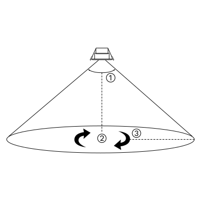
  1. 100°
  2. 360°
  3. 3-6 m

4. Installation

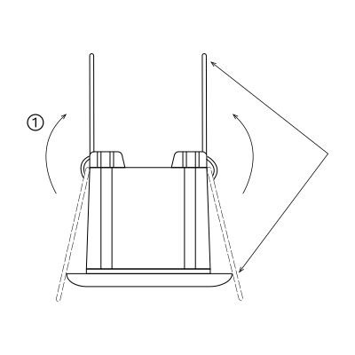
Image
  1. Choose an appropriate height - 3 meters recommended
Image
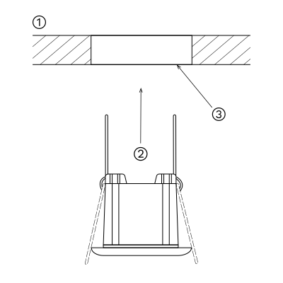
  1. Ceiling
  2. Put the motion sensor in the hole
  3. Opening hole with a diameter of 41-45 mm on the ceiling

5. Wiring

Image
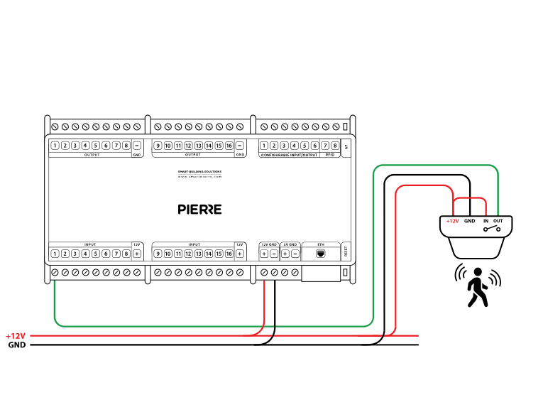
  • Connect the +12 V terminal of the sensor to the +12 V output of the controller.
  • Connect the GND terminal of the sensor to the GND terminal of the controller.
  • Bridge the IN and +12 V terminals on the sensor to enable the output switching logic.
  • Connect the OUT terminal of the sensor to a PIERRE input on the controller (e.g. INPUT 1).
Run Wires Cross-section Cable type Conductors
From motion sensor to PIERRE Controller 3 0.2 mm² (24 AWG) Cat 5e U/UTP +12 V, GND, SIGNAL

One run, three conductors — 12 V, ground and signal — on a single Cat 5e U/UTP home-run to the controller. The ceiling variant reaches about 8 m diameter at 2.5–3 m mounting height; the flush variant covers less and is limited by anything in front of it.
6. Add the Motion sensor to the App

Image
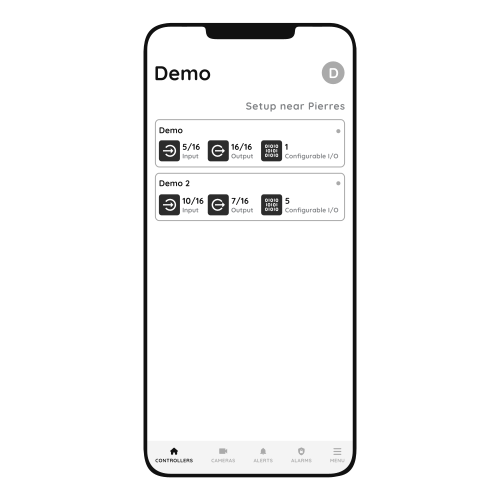
  1. Choose Controller
    1. Tap on the Controller that you would like to add new I/O to.
    2. To edit the I/O, click on the Controller to which the I/O is added.
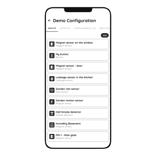
Image
  1. Add button for Inputs
    1. Inputs tab is selected.
    2. List of Inputs is shown.
    3. In order to add new Input tap on the Add button.
Image
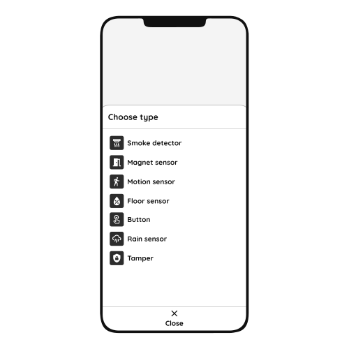
  1. Choose type - Inputs
    1. Scroll to the I/O from the list that you would like to add and tap on it.
Image
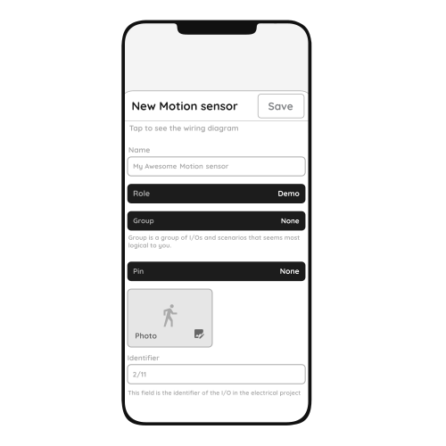
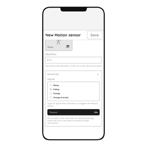
  1. New Motion sensor
    1. Fill following form:
      1. Name - Write the name of the Motion sensor.
      2. Role - Choose Role from the list.
      3. Group - Choose Group from the list. Group is a group of I/O and scenarios that seems most logical to you.
      4. Pin - Choose Pin from the list. Pin is physical place on the Controller where I/O is connected to it.
      5. Photo - Choose photo for the Motion sensor.
      6. Identifier - This field is the identifier of the I/O in the electrical project.
      7. Advanced - You can choose type of the signal that activates or triggers the Motion sensor: rising, falling, change, change inverted.
      8. Timeout - The duration for which the Motion sensor will remain active in auto mode.

When you want to confirm your choice tap button Save and Submit.
Image
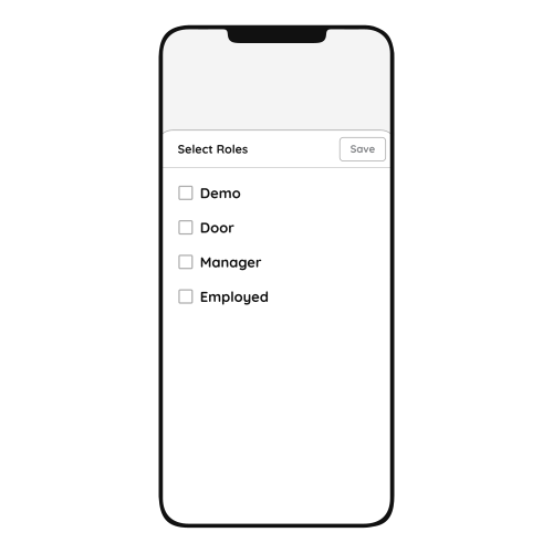
  1. Select Roles - Inputs
    1. Tap in the field Roles.
    2. Select checkbox/checkboxes (for multiple choice) next to the Role/Roles that you would like to choose.
    3. To confirm selection tap the button Save/Done.
Image
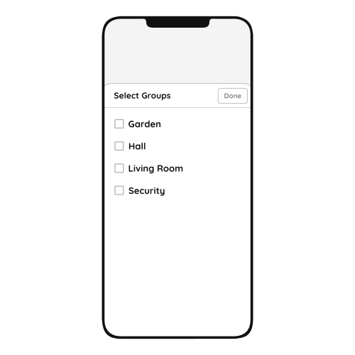
  1. Select Groups - Inputs
    1. In this step you should select Group.
    2. Select check box/check boxes next to the desired Group/Groups from the list.
    3. When you want to confirm your choice tap button Done/Save.
Image
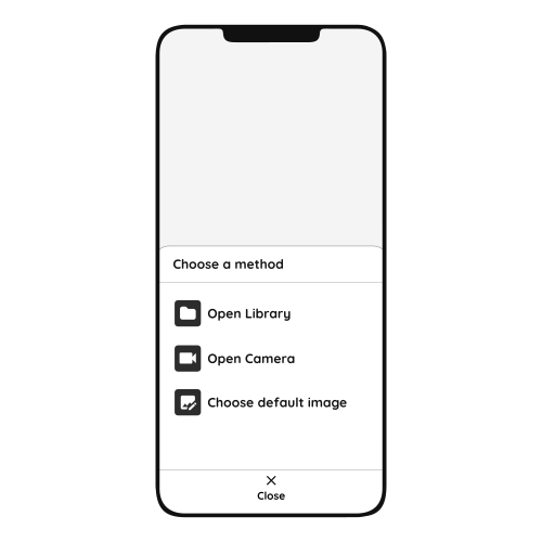
  1. Change photo
    1. Tap on the photo of the Motion sensor.
    2. You have three options:
      1. Open Library - The phone’s Library will open.
      2. Open Camera - You can take a picture using your smartphone.
      3. Choose default image - Use one of the prepared images.
Image
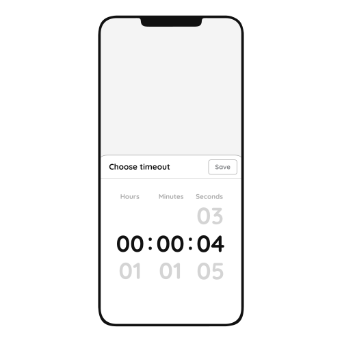
  1. Timeout
    1. In order to set Timeout - hours, minutes and seconds, you should scroll through each of these columns and when you are satisfied with your choice tap on Save button.
Image
  1. Advanced Configuration
    1. Select radio button next to the Signal that you would like to choose:
      1. Rising
      2. Falling
      3. Change
      4. Change inverted
    2. It is a type of signal that activates or triggers the Motion sensor.

7. Video

Wiring and commissioning the wired motion sensor. https://www.youtube.com/watch?v=z67GN_j-NyU

8. FAQ

Q1: What do the controller LED colours mean?

Green – online and connected. Red – offline, no network or no internet. Light blue – AP mode, broadcasting its own network for setup. Dark blue – AP mode managed through PIERRE Partner. Purple – searching for an IP address from the router. Orange – downloading a firmware update.

Q2: The sensor does not react in the app. What should I check first?

Check that the sensor has been added to the configuration in the PIERRE Partner application.

Q3: The sensor was just added and shows no state. Why?

A newly added sensor needs a state change before it reports. Trigger it, then let it go idle again.

Q4: How do I check that the sensor is wired correctly?

It must be connected to 12 V, GND and a PIERRE input as shown in the wiring diagram, with the IN terminal bridged to +12 V.

Q5: How do I find out whether the fault is in the sensor or in the cable?

Briefly bridge 12 V to the PIERRE input the sensor uses. If the dot turns green in the app, the controller and the configuration are fine and the fault is the sensor or a broken wire.

Q6: When should input and output be on the same controller?

If one input influences an output, both should be added to the same controller. A motion sensor triggering a lamp, for example, performs best when both sit on the same controller.

Q7: What is the difference between presence and motion sensors?

A motion sensor detects movement and suits high-traffic areas like hallways. A presence sensor detects that someone is in the room even when stationary, which suits offices and living areas.

Q8: How should the sensors be wired?

Each sensor is wired individually back to the PIERRE cabinet in a star pattern. INPUT 12–24 V takes 12 V DC from the controller, GND takes ground from the controller, switch terminal K1 (IN) is bridged to INPUT 12–24 V, and switch terminal K2 (OUT) goes to the input on the controller.