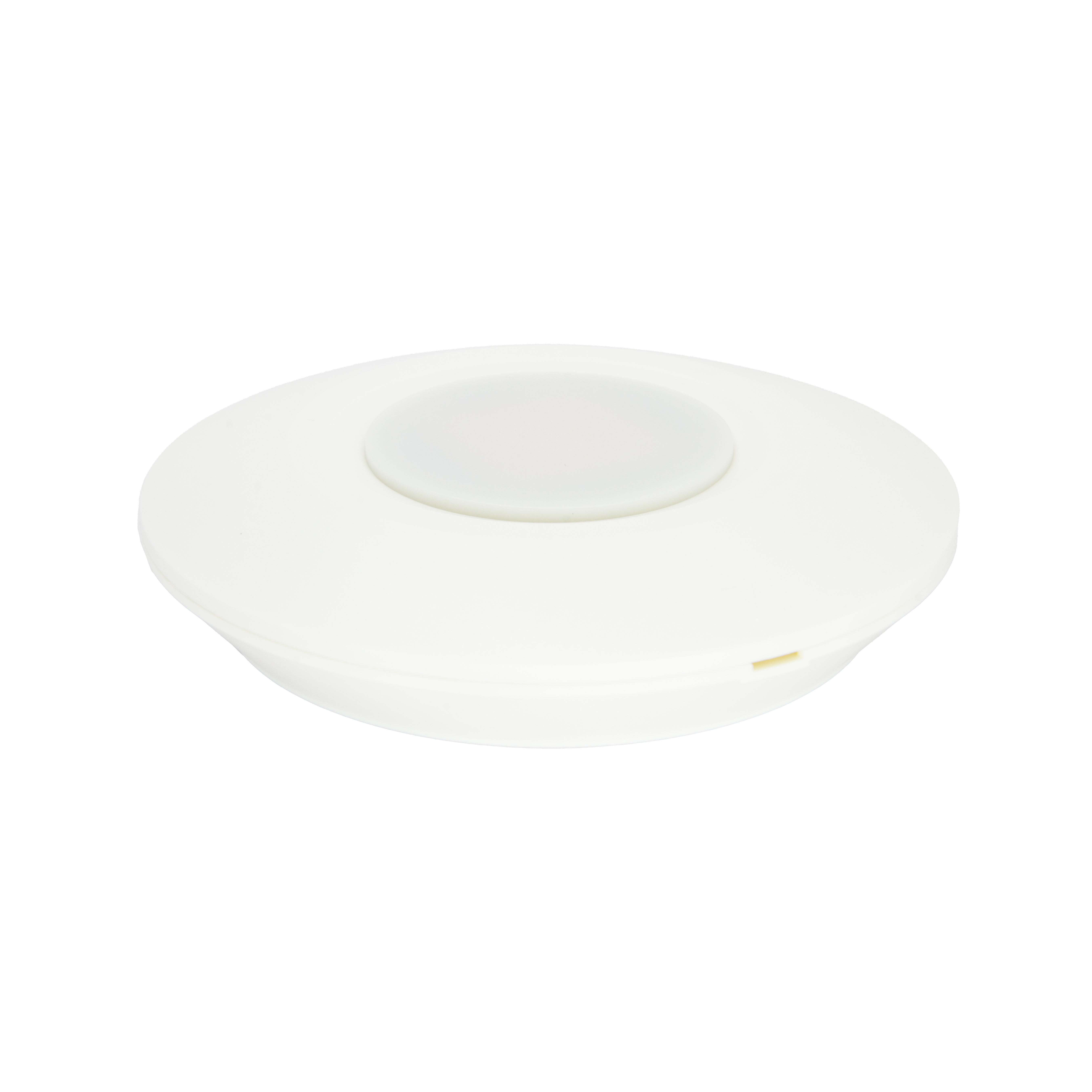
User Manual
Presence Sensor 360 (Ceiling Mount)
SKU: PP-SNS-PRESENCE-C
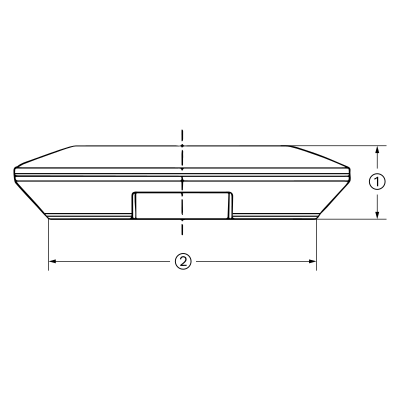
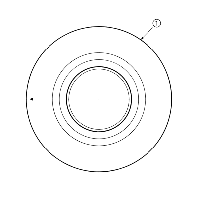
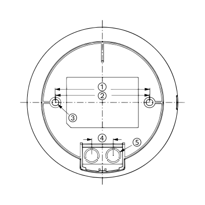
Wired. Needs a PIERRE PRO or LITE Controller with a free input, plus the Presence Sensor 360 (Ceiling Mount).
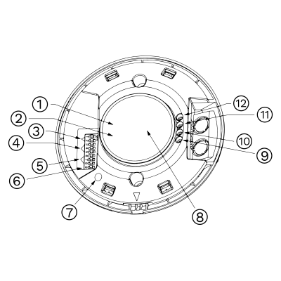
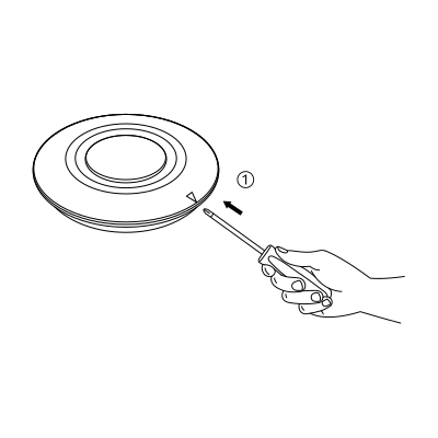
Caution: Do not use excessive force. Use only insulated tools and follow local electrical safety regulations.
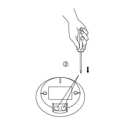
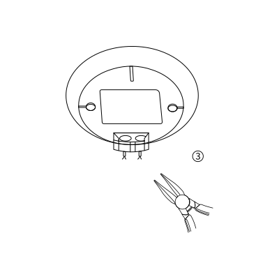
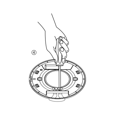
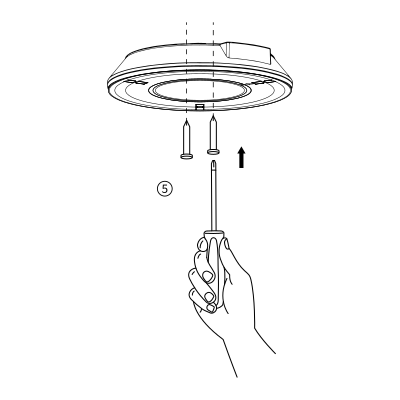
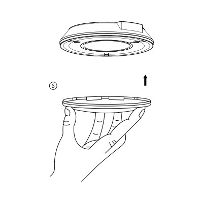
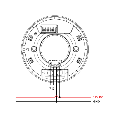
The sensor has four terminals: P1, P2, GND and 12V.
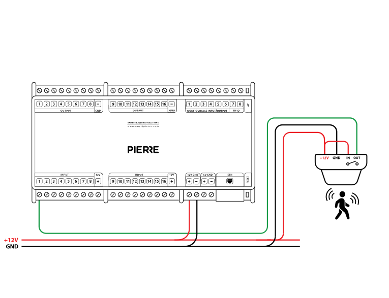
| Run | Wires | Cross-section | Cable type | Conductors |
|---|---|---|---|---|
| From presence sensor to PIERRE Controller | 3 | 0.2 mm² (24 AWG) | Cat 5e U/UTP | +12 V, GND, SIGNAL |
One run, three conductors — 12 V, ground and signal — on a single Cat 5e U/UTP home-run to the controller. Identical to the motion sensor run; only the mounting and the detection behaviour differ.
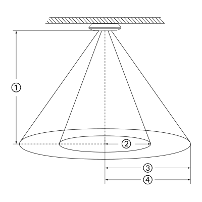
Signal detection: The sensor detects walking, slight movements (such as body shifts, head turns, and other minor actions), and breathing to identify human presence during a non-sleep state.

Movement signal: Large or noticeable movement that activates the sensor
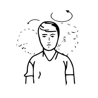
Slight motion signal: When only very small body movements are detected, the indicator flashes once.

Breathing signal: When no slight motion is detected, only the breathing signal is collected. The indicator flashes three times after detecting three valid breathing signals.
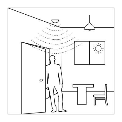
When the ambient light is sufficient, the light will not turn on even if motion is detected.
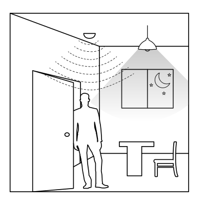
When the ambient light is low, motion is detected and the light turns on automatically.
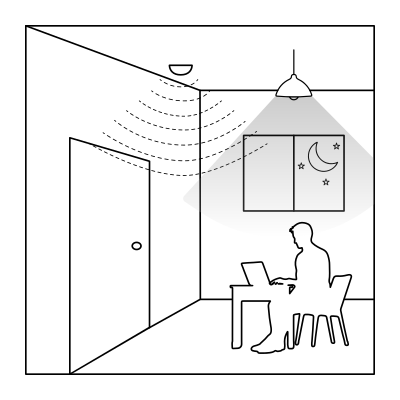
Movements like the body, head, and other small actions are detected during normal use, the light stays on continuously.

When the sensor fails to detect movement or slight motion, the light will automatically turn off after the set delay time
Detection Area
DIP switches 1 and 2 set the sensitivity, i.e. the size of the detection area.
| Position | 1 | 2 | Detection area |
|---|---|---|---|
| I | ON | ON | 100% |
| II | - | ON | 75% |
| III | ON | - | 50% |
| IV | - | - | 25% |
Hold Time
DIP switches 3, 4 and 5 set how long the output stays active after motion is detected.
Note: To enable presence detection (breathing detection), set the hold time to at least 1 minute, preferably longer. The 5-second setting is intended for motion-sensor testing only.
| Position | 3 | 4 | 5 | Hold time |
|---|---|---|---|---|
| I | ON | ON | ON | 5s |
| II | ON | - | ON | 30s |
| III | ON | ON | - | 1 min |
| IV | ON | - | - | 3 min |
| V | - | ON | ON | 5 min |
| VI | - | - | ON | 10 min |
| VII | - | ON | - | 20 min |
| VIII | - | - | - | 30 min |
Daylight Sensor
This table shows how DIP switches 6, 7 and 8 control the daylight (ambient light) threshold. This setting determines when the sensor is allowed to turn on the light, based on the surrounding brightness level.
Note: When set to "Disable", the sensor will turn on the light whenever it detects movement, regardless of the ambient light level.
| Position | 6 | 7 | 8 | Threshold |
|---|---|---|---|---|
| I | ON | ON | ON | 5 Lux |
| II | - | ON | ON | 30 Lux |
| III | ON | - | ON | 50 Lux |
| IV | - | - | ON | 100 Lux |
| V | ON | ON | - | 150 Lux |
| VI | - | - | - | Disable |
Indicator light
DIP switch 9 controls whether the indicator LED on the sensor is ON or OFF.
HS: The indicator light is on.
LS: The indicator light is off.
Note: The indicator is ON by default. It can be turned OFF using the DIP switch or by pressing the LS button on the remote control.
| 9 | |||
|---|---|---|---|
| I | ON | Indicator on (HS) | |
| II | - | Close |
When powered on for the first time, the sensor enters a self-test mode. This process lasts 20 seconds, after which the sensor switches to normal operation.
During initialization, external motion signals are not detected and remote control signals are ignored.
Note: Detection area settings should be adjusted according to the actual environment. The above examples are for reference only.
Green – online and connected. Red – offline, no network or no internet. Light blue – AP mode, broadcasting its own network for setup. Dark blue – AP mode managed through PIERRE Partner. Purple – searching for an IP address from the router. Orange – downloading a firmware update.
Check that the sensor has been added to the configuration in the PIERRE Partner application.
A newly added sensor needs a state change before it reports. Trigger it, then let it go idle again.
It must be connected to 12 V, GND and a PIERRE input as shown in the wiring diagram, with the IN terminal bridged to +12 V.
Briefly bridge 12 V to the PIERRE input the sensor uses. If the dot turns green in the app, the controller and the configuration are fine and the fault is the sensor or a broken wire.
If one input influences an output, both should be added to the same controller. A motion sensor triggering a lamp, for example, performs best when both sit on the same controller.
A motion sensor detects movement and suits high-traffic areas like hallways. A presence sensor detects that someone is in the room even when stationary, which suits offices and living areas.
Each sensor is wired individually back to the PIERRE cabinet in a star pattern. INPUT 12–24 V takes 12 V DC from the controller, GND takes ground from the controller, switch terminal K1 (IN) is bridged to INPUT 12–24 V, and switch terminal K2 (OUT) goes to the input on the controller.