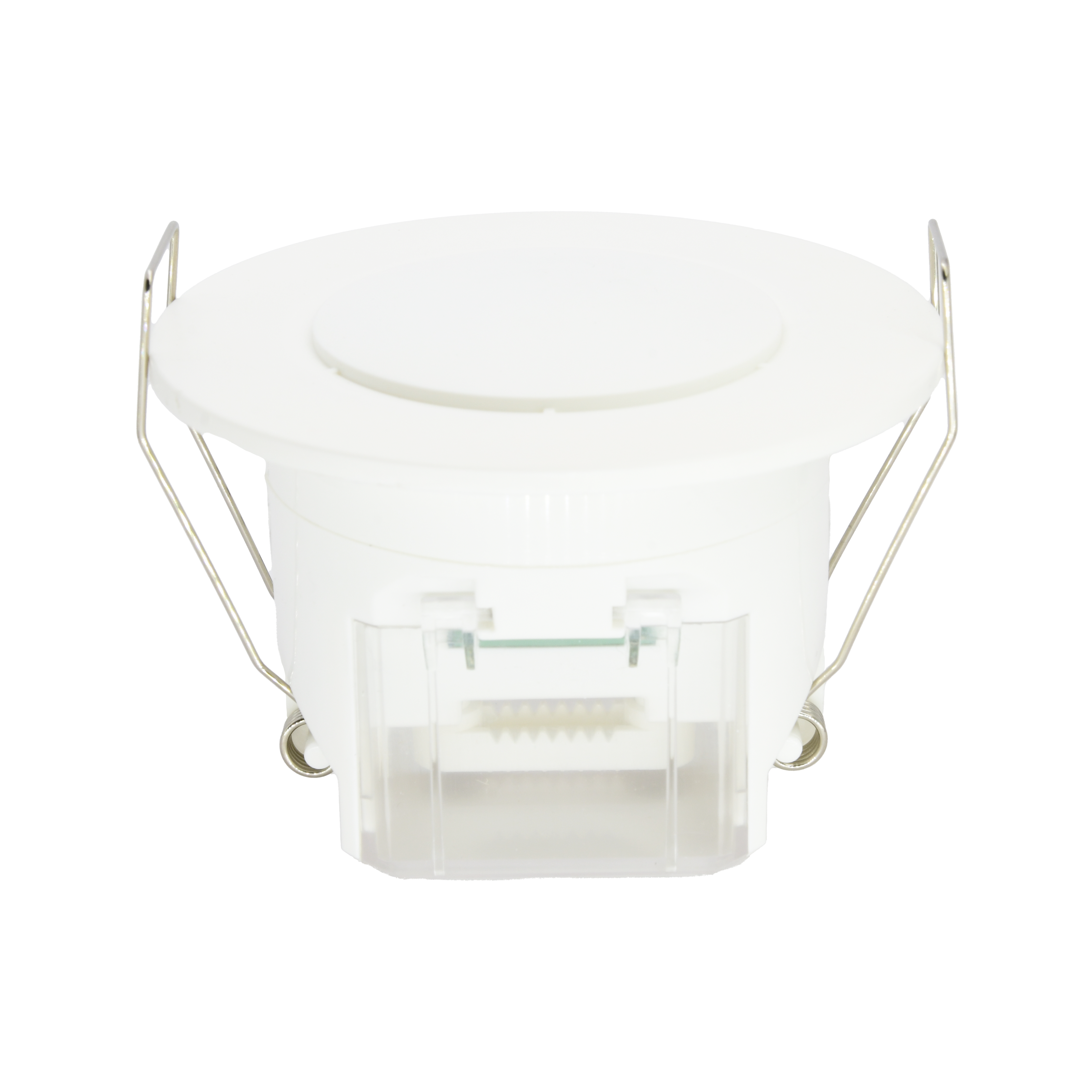
Presence Sensor 360 (Flush Mount)
User Manual

Presence Sensor 360 (Flush Mount)

SKU: PP-SNS-PRESENCE-F
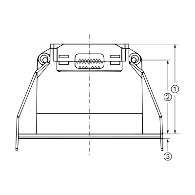
1. Dimensions

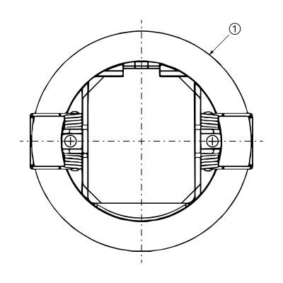
Image
  1. 52.50 mm
  2. 43.20 mm
  3. 2.50 mm
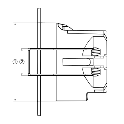
Image
  1. Φ 85.00 mm
Image
  1.  62.00 mm
  2. 21.60 mm

2. What you need

Wired. Needs a PIERRE PRO or LITE Controller with a free input, plus the Presence Sensor 360 (Flush Mount).

3. Functions

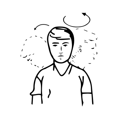
Signal detection: The sensor detects walking, slight movements (such as body shifts, head turns, and other minor actions), and breathing to identify human presence during a non-sleep state.

Image

Movement signal: Large or noticeable movement that activates the sensor
Image

Slight motion signal: When only very small body movements are detected, the indicator flashes once.

Image

Breathing signal: When no slight motion is detected, only the breathing signal is collected. The indicator flashes three times after detecting three valid breathing signals.
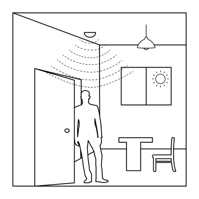
Image

When the ambient light is sufficient, the light will not turn on even if motion is detected.
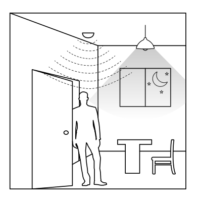
Image

When the ambient light is low, motion is detected and the light turns on automatically.
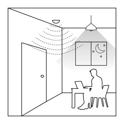
Image

Movements like the body, head, and other small actions are detected during normal use, the light stays on continuously.
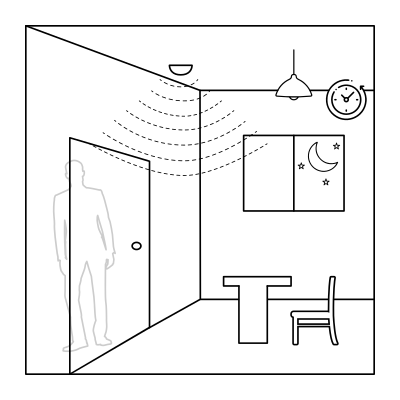
Image

When the sensor fails to detect movement or slight motion, the light will automatically turn off after the set delay time
4. Structure

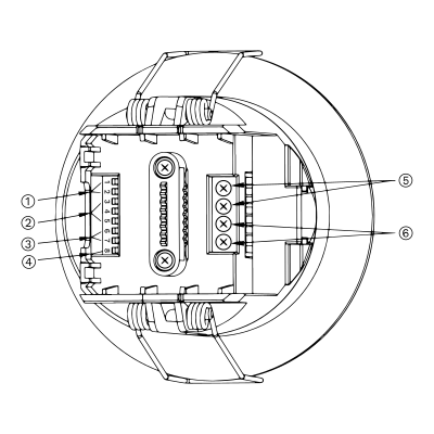
Image
  1. Adjustable detection area
  2. Hold-time
  3. Daylight threshold
  4. Minor motion indicator
  5. Switch
  6. 12/24V DC Input

5. Installation

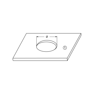
Image
  1. Cut a hole of 65–70 mm in the ceiling
Image
  1. Turn the rotating protective cover fully open
Image
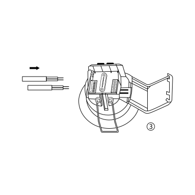
  1. Wiring (input & output)
Image
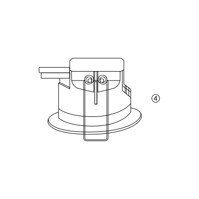
  1. Fit the cable clamp screw and turn the protective cover back onto the housing
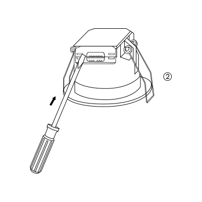
Image
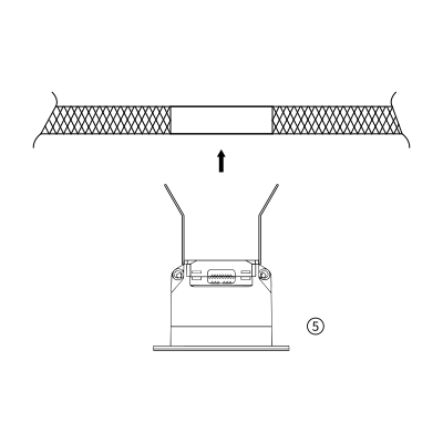
  1. Bend the spring clips back and push the sensor into the pre-cut hole in the ceiling
Image
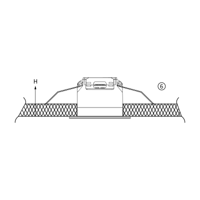
  1. Check that the sensor sits flush and firmly in the ceiling

6. Wiring

Image

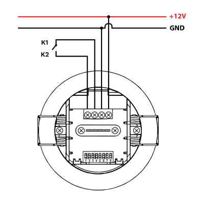
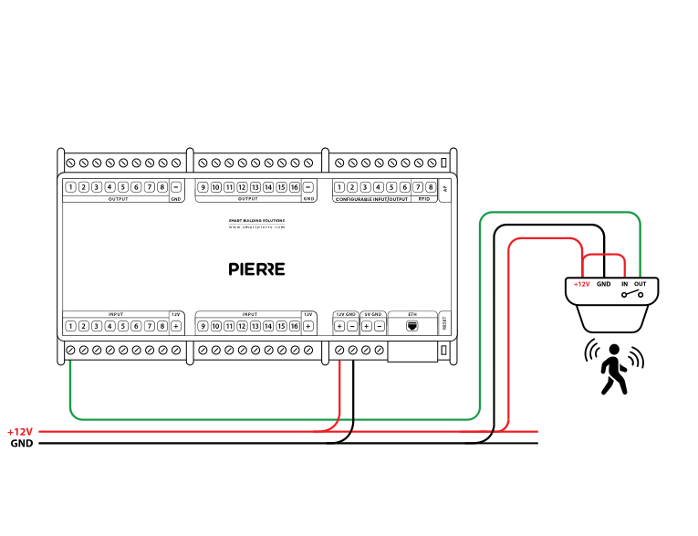
The sensor is powered with 12 V DC on the +12V and GND terminals. K1 and K2 are the two terminals of the switch contact: bridge K1 to +12 V and wire K2 to a PIERRE Controller input.
Image
  • Connect the +12 V terminal of the sensor to the +12 V output of the controller.
  • Connect the GND terminal of the sensor to the GND terminal of the controller.
  • Bridge the IN and +12 V terminals on the sensor to enable the output switching logic.
  • Connect the OUT terminal of the sensor to a PIERRE input on the controller (e.g. INPUT 1).
Run Wires Cross-section Cable type Conductors
From presence sensor to PIERRE Controller 3 0.2 mm² (24 AWG) Cat 5e U/UTP +12 V, GND, SIGNAL

One run, three conductors — 12 V, ground and signal — on a single Cat 5e U/UTP home-run to the controller. Identical to the motion sensor run; only the mounting and the detection behaviour differ.
7. Detection pattern

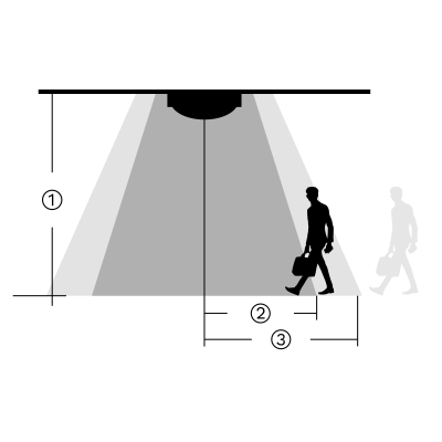
Image
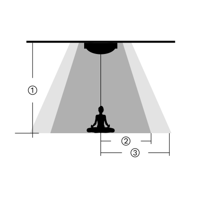
  • Movement detection speed 0.3 m/s
  1. 3.0 m
  2. 4.0 m
  3. 5.0 m
Image
  • Minor Motion Detection
  1. 3.0 m
  2. 4.0 m
  3. 5.0 m
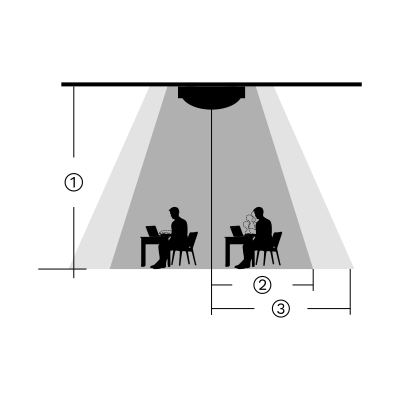
Image
  • Breathing Detection
  1. 3.0 m
  2. 3.0 m
  3. 4.0 m

8. DIP Switch settings

Detection Area

DIP switches 1 and 2 set the sensitivity, i.e. the size of the detection area.

Position12Detection area
IONON100%
II-ON75%
IIION-50%
IV--25%

Hold Time

DIP switches 3, 4 and 5 set how long the output stays active after motion is detected.

Note: To enable presence detection (breathing detection), set the hold time to at least 1 minute, preferably longer. The 5-second setting is intended for motion-sensor testing only.

Position 3 4 5 Hold time
I ON ON ON 5s
II ON - ON 30s
III ON ON - 1 min
IV ON - - 3 min
V - ON ON 5 min
VI - - ON 10 min
VII - ON - 20 min
VIII - - - 30 min

Daylight Sensor

This table shows how DIP switches 6 and 7 control the daylight (ambient light) threshold. This setting determines when the sensor is allowed to turn on the light, based on the surrounding brightness level:


Note: When set to "Disable", the sensor will turn on the light whenever it detects movement, regardless of the ambient light level.

Position 6 7 Threshold
I ON ON 5 Lux
II ON - 25 Lux
III - ON 50 Lux
IV - - Disabled

Indicator Light

This setting, DIP switch 8, controls whether the indicator LED on the sensor is ON or OFF.


HS: The indicator light is on.

LS: The indicator light is off.


Note: The indicator is ON by default. It can be turned OFF using the DIP switch or by pressing the LS button on the remote control.

8
I ON Indicator on (HS)
II - Close

9. Initialization

When powered on for the first time, the sensor enters a self-test mode. This process lasts 20 seconds, after which the sensor switches to normal operation.

During initialization, external motion signals are not detected and remote control signals are ignored.
10. Factory Settings

  • Indicator Light: On
  • Detection Area: 100%
  • Hold Time: 1 minute
  • Daylight Sensor: Disabled

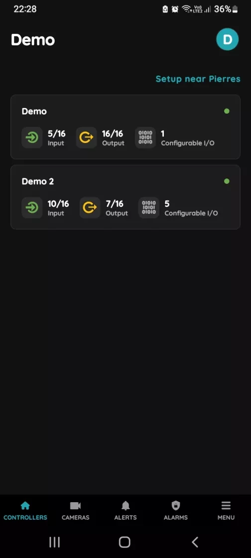
11. Add the Presence sensor to the App

Image
  1. Choose Controller
    1. Tap on the Controller that you would like to add new I/O to.
    2. To edit the I/O, click on the Controller to which the I/O is added.
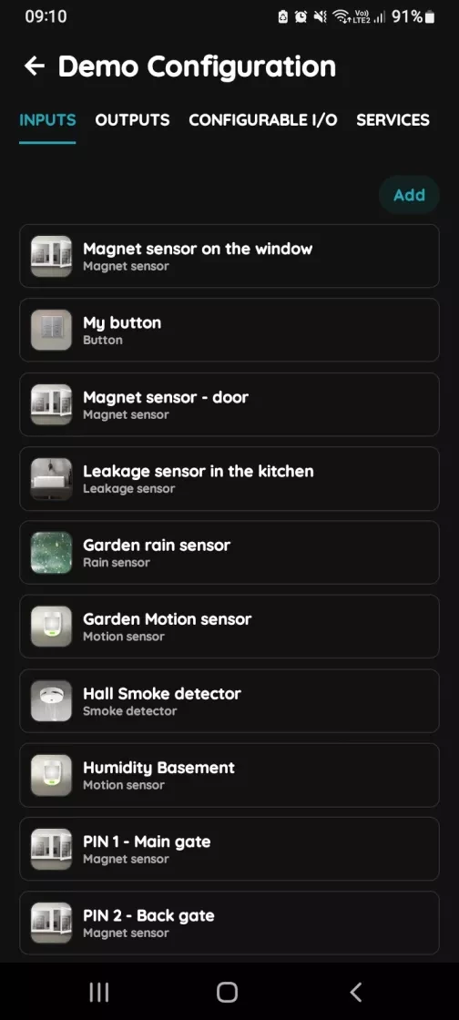
Image
  1. Add button for Inputs
    1. Inputs tab is selected.
    2. List of Inputs is shown.
    3. In order to add new Input tap on the Add button.
Image
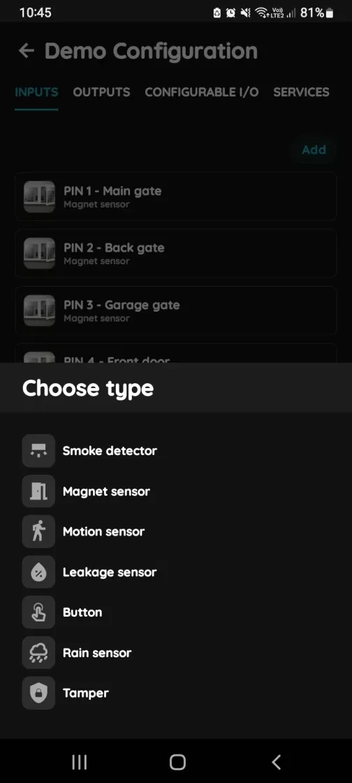
  1. Choose type - Inputs
    1. Scroll to the I/O from the list that you would like to add and tap on it.
Image
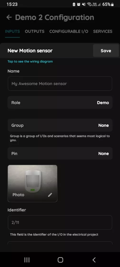
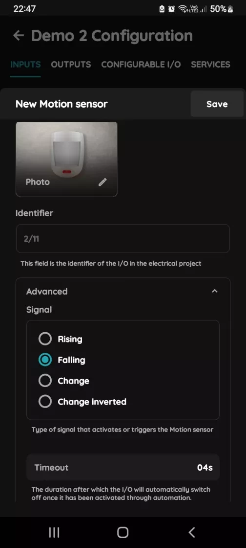
  1. New Motion sensor
    1. Fill following form:
      1. Name - Write the name of the Motion sensor.
      2. Role - Choose Role from the list.
      3. Group - Choose Group from the list. Group is a group of I/O and scenarios that seems most logical to you.
      4. Pin - Choose Pin from the list. Pin is physical place on the Controller where I/O is connected to it.
      5. Photo - Choose photo for the Motion sensor.
      6. Identifier - This field is the identifier of the I/O in the electrical project.
      7. Advanced - You can choose type of the signal that activates or triggers the Motion sensor: rising, falling, change, change inverted.
      8. Timeout - The duration for which the Motion sensor will remain active in auto mode.
    2. When you want to confirm your choice tap button Save and Submit.
Image
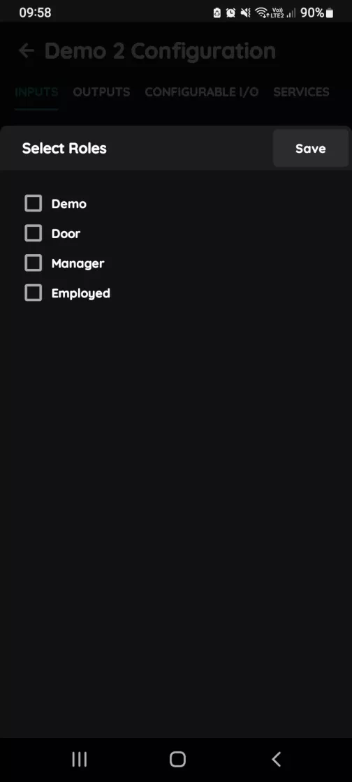
  1. Select Roles - Inputs
    1. Tap in the field Roles.
    2. Select checkbox/checkboxes (for multiple choice) next to the Role/Roles that you would like to choose.
    3. To confirm selection tap the button Save/Done.
Image
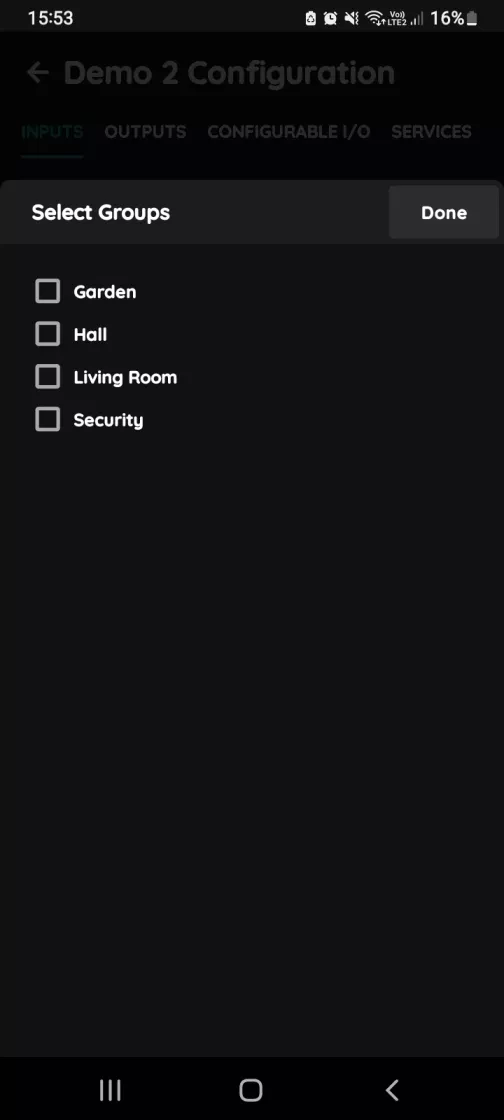
  1. Select Groups - Inputs
    1. In this step you should select Group.
    2. Select check box/check boxes next to the desired Group/Groups from the list.
    3. When you want to confirm your choice tap button Done/Save.
Image
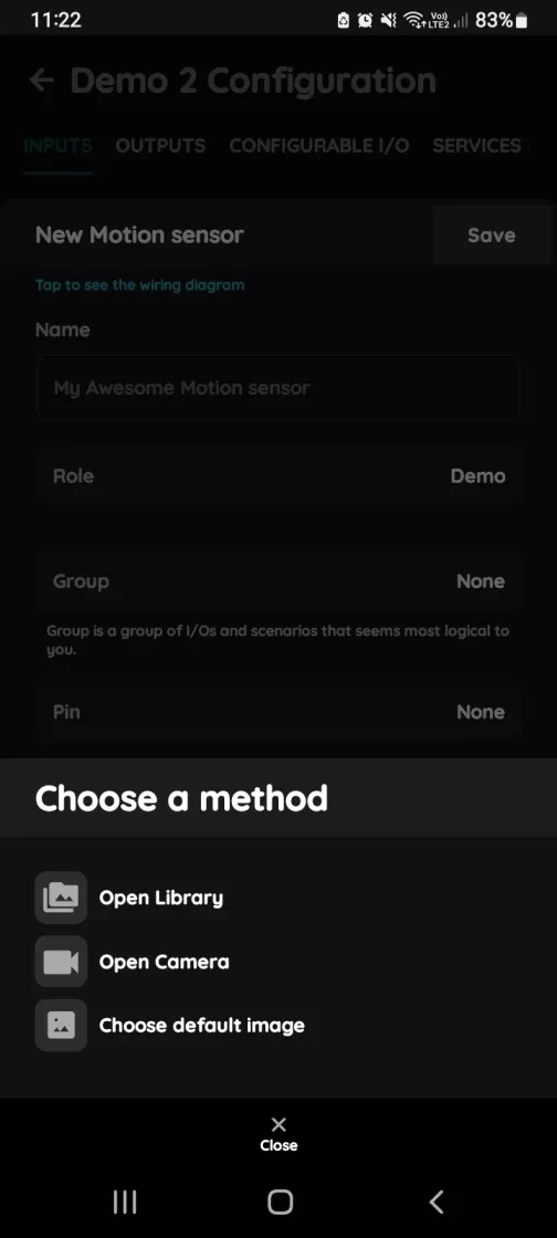
  1. Change photo
    1. Tap on the photo of the Motion sensor.
    2. You have three options:
      1. Open Library - The phone’s Library will open.
      2. Open Camera - You can take a picture using your smartphone.
      3. Choose default image - Use one of the prepared images.
Image
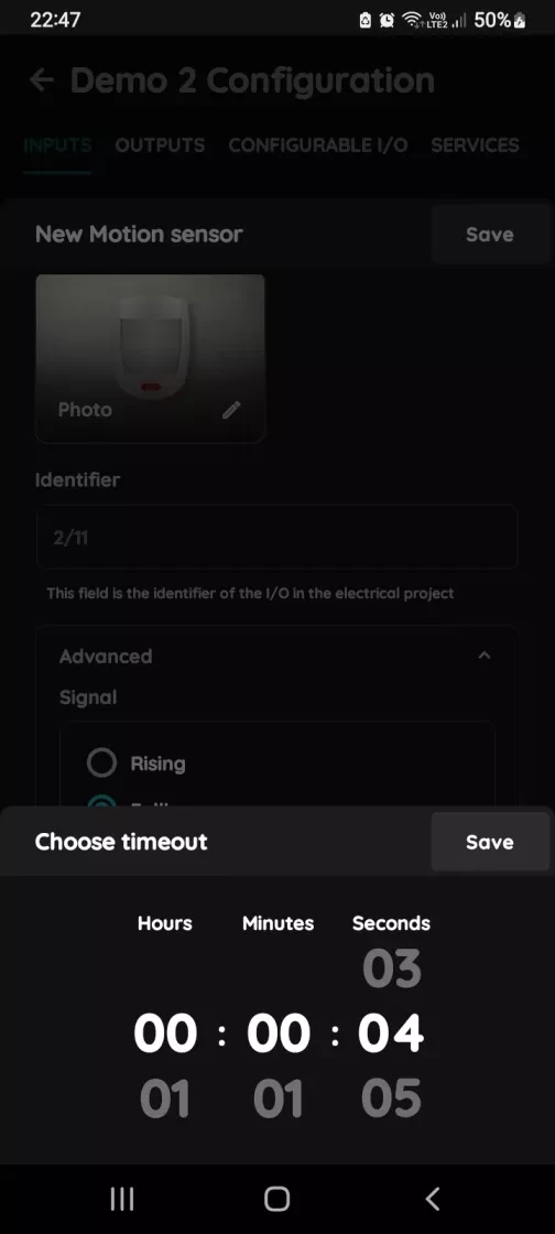
  1. Timeout
    1. In order to set Timeout - hours, minutes and seconds, you should scroll through each of these columns and when you are satisfied with your choice tap on Save button.
Image
  1. Advanced Configuration
    1. Select radio button next to the Signal that you would like to choose:
      1. Rising
      2. Falling
      3. Change
      4. Change inverted
    2. It is a type of signal that activates or triggers the Motion sensor.

12. Installation Notes and Precautions

  1. Professional Installation Required:
    1. The sensor must be installed by a qualified electrician. Make sure to disconnect the power supply before installation, wiring, or adjusting the DIP switch settings.
  2. Avoid High-Density Materials:
    1. Install the sensor away from large metal surfaces, glass panels, or other materials with high medium density, as these can cause false triggers.
  3. Avoid Constant Vibrations:
    1. Do not place the sensor near objects that vibrate continuously (e.g. ceiling fans), as vibration signals may be misinterpreted as motion, leading to false activation.
  4. Prevent Light Interference:
    1. Make sure that the daylight sensor’s detection window is not exposed to invalid or stray light sources, as this can interfere with accurate ambient light detection.
  5. Microwave Penetration Warning:
    1. The microwave sensor can penetrate walls. Movement outside the intended detection area (e.g. behind thin walls) may cause false alarms. To prevent this, carefully choose the installation location and adjust the detection range appropriately.
  6. Detection Range Disclaimer:
    1. The detection pattern and range are based on typical factory testing. Actual performance may vary depending on movement speed, mounting height, type of moving object, and environmental conditions.

13. FAQ

Q1: What do the controller LED colours mean?

Green – online and connected. Red – offline, no network or no internet. Light blue – AP mode, broadcasting its own network for setup. Dark blue – AP mode managed through PIERRE Partner. Purple – searching for an IP address from the router. Orange – downloading a firmware update.

Q2: The sensor does not react in the app. What should I check first?

Check that the sensor has been added to the configuration in the PIERRE Partner application.

Q3: The sensor was just added and shows no state. Why?

A newly added sensor needs a state change before it reports. Trigger it, then let it go idle again.

Q4: How do I check that the sensor is wired correctly?

It must be connected to 12 V, GND and a PIERRE input as shown in the wiring diagram, with the IN terminal bridged to +12 V.

Q5: How do I find out whether the fault is in the sensor or in the cable?

Briefly bridge 12 V to the PIERRE input the sensor uses. If the dot turns green in the app, the controller and the configuration are fine and the fault is the sensor or a broken wire.

Q6: When should input and output be on the same controller?

If one input influences an output, both should be added to the same controller. A motion sensor triggering a lamp, for example, performs best when both sit on the same controller.

Q7: What is the difference between presence and motion sensors?

A motion sensor detects movement and suits high-traffic areas like hallways. A presence sensor detects that someone is in the room even when stationary, which suits offices and living areas.

Q8: How should the sensors be wired?

Each sensor is wired individually back to the PIERRE cabinet in a star pattern. INPUT 12–24 V takes 12 V DC from the controller, GND takes ground from the controller, switch terminal K1 (IN) is bridged to INPUT 12–24 V, and switch terminal K2 (OUT) goes to the input on the controller.