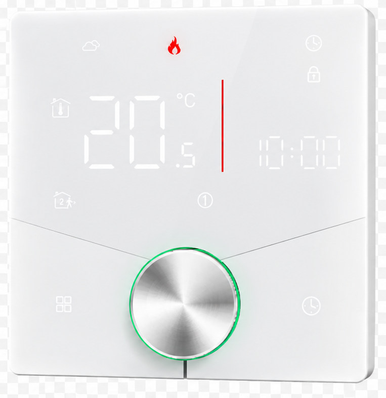
User Manual
PIERRE T2 - Dry Contact Thermostat (24V, White)
SKU: PP-T-MODBUS-WHI-24V
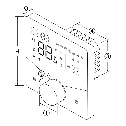
H: 88 mm
Wired. Needs a PIERRE Pro Controller plus a Modbus (TTL to RS-485) converter.
The PIERRE T2 thermostat is made in two communication versions and two supply voltages. This manual covers the Modbus RTU version for PIERRE Pro installations; a Zigbee version exists for PIERRE Wave installations. Each version is supplied for either 24 V or 230 V AC (L, N). The version must match the communication method and the supply voltage of the installation, and a thermostat must only be connected to the supply voltage it is rated for.
The T2 works as a room thermostat on its own: the user sets the temperature at the thermostat and its relay output switches the heating or cooling circuit. Once it is connected to the PIERRE system over Modbus RTU or Zigbee, its temperature, set point and mode become available for central control, the Smart PIERRE app, PIERRE displays, scenes, schedules and automations. Local operation keeps working when the connection is down.
The Modbus version connects by wire: T2 thermostat → Modbus RTU (A+, B−) → TTL to RS-485 converter → PIERRE Pro Controller. Several thermostats share one bus; each needs its own Modbus address (function 14) and the same baud rate (function 15). The bus is a shielded twisted pair, terminated at both ends. Wiring details are in the Wiring section.
The Zigbee version needs no communication cable: T2 thermostat → Zigbee → a PIERRE display and/or gateway → PIERRE system. It is powered from its 24 V or 230 V supply and paired with the gateway from the Smart PIERRE app. Zigbee range is reduced by distance, reinforced-concrete walls and floors; where coverage is weak, use Zigbee repeaters or additional gateways, and plan the gateway positions during system design in large or multi-storey buildings.
Two arrangements are possible:
| PIERRE Pro | PIERRE Wave | |
|---|---|---|
| Communication | Modbus RTU (wired) | Zigbee (wireless) |
| Supply voltage | 24 V or 230 V AC | 24 V or 230 V AC |
| Required PIERRE device | PIERRE Pro Controller + TTL to RS-485 converter | A PIERRE display and/or gateway |
| Communication cable | Required | Not required |
| Local thermostat operation | Yes | Yes |
| App access, scenes, automations | When integrated | When integrated |
| Relay Type | Dry Contact |
| Number of Channels | 2 channels |
| Power Supply | 24V AC 50-60Hz |
| Power Consumption | 1.50 W |
| Connectivity | Zigbee, Modbus |
| Built-in Sensors | Temperature, Humidity |
| Temperature Accuracy | ±1 °C |
| Operating Temperature (°C) | 0 - +40 |
| Operating Humidity | 5% - 95% RH Non condensing % RH |
| Storage Temperature | +5°C to +45°C |
| IP Rating | IP20 |
| Warranty | 2 years |
| Panel Material | ABS+PC material |
| Product Color | White |
| Mounting Type | Wall mount |
| Mounting Box | 86x86x50mm |
| Bolt Hole Distance | 60 mm |
| Wiring Requirements | N - Neutral, L - Live |
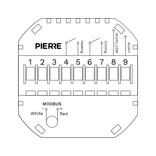
PIERRE T2 Modbus thermostat — underfloor heating / ceiling cooling
| Run | Wires | Cross-section | Cable type | Conductors |
|---|---|---|---|---|
| From controller to MODBUS converter | 4 | 0.2 mm² (24 AWG) | Cat 5e U/UTP | 12 V, GND, TTL TX, TTL RX |
| From 24 V power supply to MODBUS thermostat | 2 | 0.75 mm² | 2-core, low voltage | 24 V, GND |
| From MODBUS converter to MODBUS thermostat (bus) | 2 | 0.75 mm² | Shielded twisted pair | A+, B− |
Controller to converter is four conductors: 12 V, GND and the two TTL data lines. The 24 V supply reaches the thermostat on two conductors. The Modbus bus itself is a two-conductor pair, A+ and B−: use shielded twisted pair in a bus topology, terminated at both ends of the line.
The 24 V supply and the Modbus bus may also share one shielded 4-core cable: two conductors for 24 V and GND, two for A+ and B−.
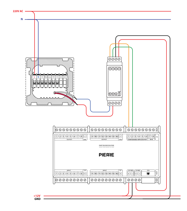
PIERRE T2 Modbus thermostat — wiring diagram
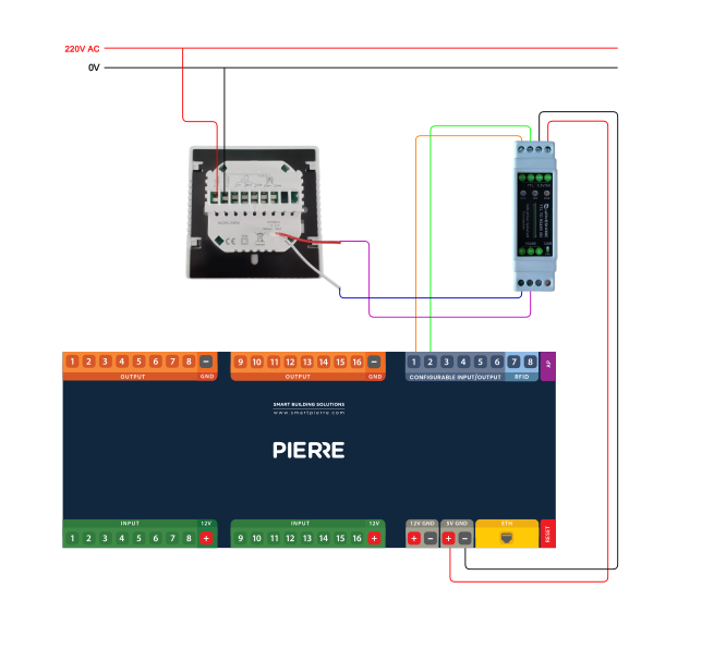
PIERRE T2 Modbus thermostat — wiring example
This Thermostat is suitable for installation within a standard 86 mm or European 60 mm wall box.
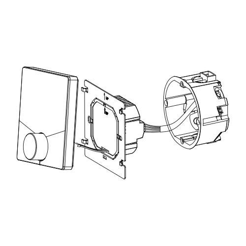
Connect the power cable to the power terminals.
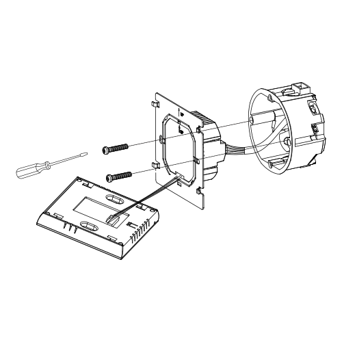
Fix the mounting plate to the wall box with two screws.
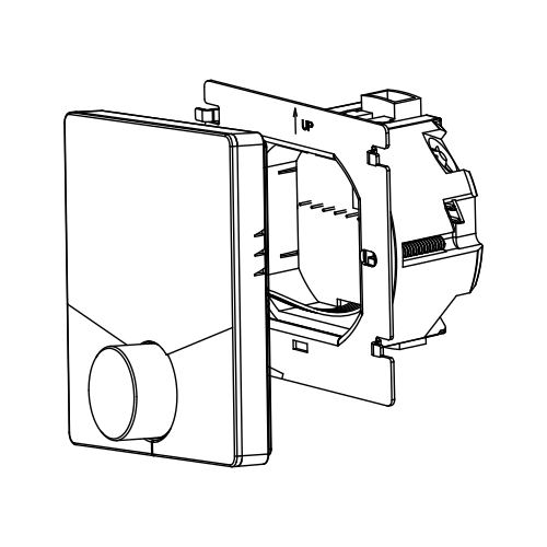
Hang the control panel onto the mounting plate
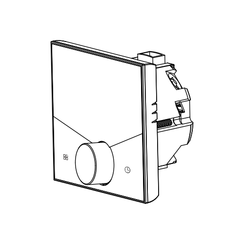
Installation is completed
During Power On
1. Power On/off:
Press the Center Knob to turn the thermostat on/off.
2. Manual & Programmable
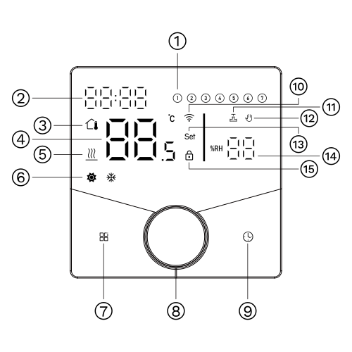
Press the Mode button to change between manual mode (🔥) and programme mode (🕒).
3. Setting Temperature
In the programming mode, the temperature setting and time setting will be locked. To adjust them, first switch the thermostat to manual mode by pressing the Mode button.
In the manual mode, the desired temperature can be set by turning the Center Knob.
4. Adjusting/Setting the Clock
Press 🕒 to set minute, hour and weekday, and adjust the values by turning the Center Knob.
Press the Mode button once more to confirm and exit.
5. Locking your Thermostat
Press and hold the Mode button and 🕒 for 5 seconds to lock/unlock your thermostat.
Full lock or partial lock is selected with function 4 (Button locking) in the function settings (see 8).
6. Adjusting/Setting the Programmable Schedules
Press icon 🕒 four times in a row. You can see "MON TUE WED THU FRI" and the minutes of time are flashing.
This completes the setting of Period 1.
In the same way, complete the settings of the remaining periods.
Press the icon 🕒 once more to enter the Saturday schedule settings (you will see the SAT on the screen).
Repeat the above process to set the period and temperature, and Sunday schedule.
Press the icon 🕒 once more to confirm and exit.
| Time display | MON–FRI (①②③④⑤ shows on screen) | SAT. (⑥ shows on screen) | SUN. (⑦ shows on screen) |
|---|---|---|---|
| Period 1 | 6:00 20 °C | 6:00 20 °C | 6:00 20 °C |
| Period 2 | 11:30 20°C | 11:30 20°C | 11:30 20°C |
| Period 3 | 13:30 20°C | 13:30 20°C | 13:30 20°C |
| Period 4 | 17:30 20°C | 17:30 20°C | 17:30 20°C |
A separate schedule may be set for weekdays (Mon–Fri) and for weekends (Sat and Sun).
Press and hold the 🕒 button for 5 seconds to display the temperature of the floor sensor.
If no external sensor is connected, the thermostat will display "Er".
⚠ Note: Do not use third-party external sensors; the temperature will be incorrect.
During power off, press and hold the Mode button and 🕒 for 8 seconds in order to reach system function.
Then press the Mode button to scroll through the available functions, and turn the Center Knob to change the available options.
All settings are confirmed automatically.
| Code | Function | Setting and options | Default |
|---|---|---|---|
| 1 | Temperature compensation | -9 to 9 °C (for internal sensor) | -3 |
| 2 | Humidity compensation | -9 to 9 | 01 |
| 3 | Deadzone temperature | 1–5 °C | 01 |
| 4 | Button locking | 00: All buttons are locked except power button. 01: All buttons are locked. | 01 |
| 5 | Sensor type | In: Internal sensor (to control the temp.) Ou: External sensor (to control the temp.) AL: Internal/External sensor (internal sensor to control temp. external sensor to limit temp.) | AL |
| 6 | Min. set temp. | 5–15 °C | 05 |
| 7 | Max. set temp. | 30–45 °C | 35 |
| 8 | Display mode | 00: Display both set temp. and room temp. 01: Display set temp. only | 00 |
| 9 | Bright duty Day | 0–8 | 03 |
| 10 | Bright duty Night | 0–8 | 01 |
| 11 | Screen dividing line standby brightness | 1–5 | 01 |
| 14 | Modbus RTU Slave address | 1–255 | 01 |
| 15 | Modbus Baud rate (9600/ 19200/ 38400/ 57600/ 115200) | 1–5 | 01 |
| 16 | Reset | 00: No factory reset 01: Factory reset | 00 |
| 17 | Version number | Firmware version | U3 |
Check first that it is properly connected and powered.
Check that it has been added to the configuration in the PIERRE Partner app.
The temperature sensor is faulty. Check the sensor type setting (function 5) and the external sensor connection.
Yes — temperature is controlled room by room.