User Manual
Temperature Sensor
SKU: PP-TEMP
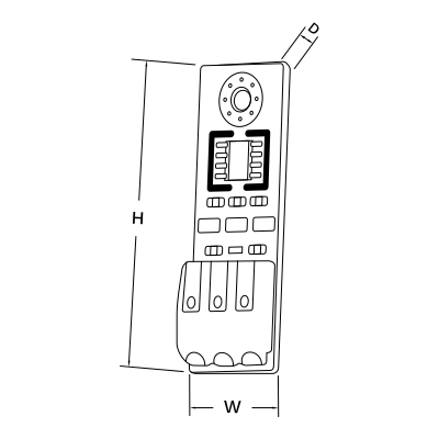
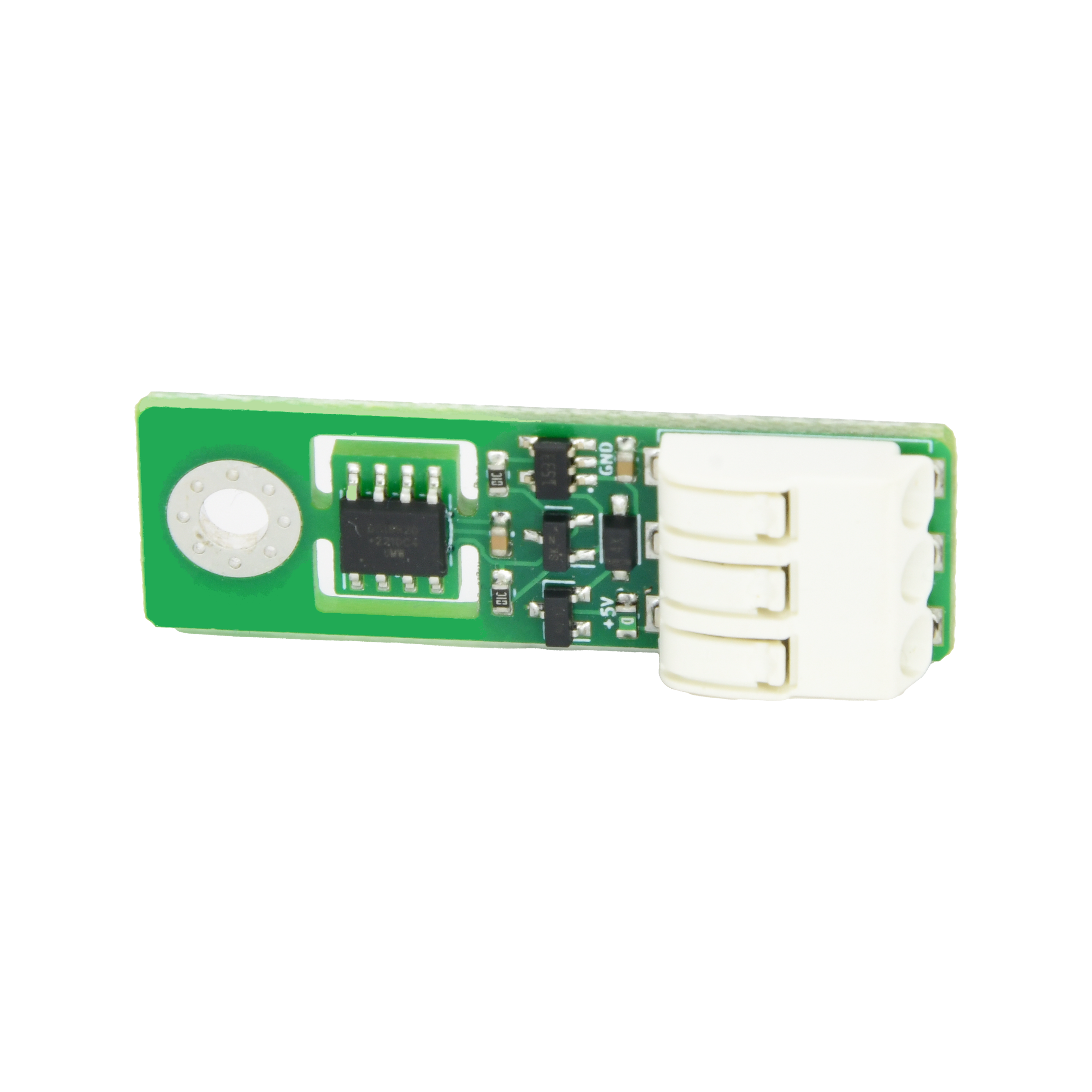
Wired. Needs a PIERRE PRO or LITE Controller with a free Configurable I/O (digital) pin, plus the Temperature Sensor. The sensor is powered from the controller’s 5 V rail.
| Operating Temperature | -67°F - +257°F |
| Operating Temperature (°C) | -55 - +125 |
| Operating Humidity | Non condensing, 5 - 90 % RH |
| Altitude | <3000m |
| Safety Features | Over Voltage, Short Circuit, Reverse polarity |
| Built-in Sensors | Temperature |
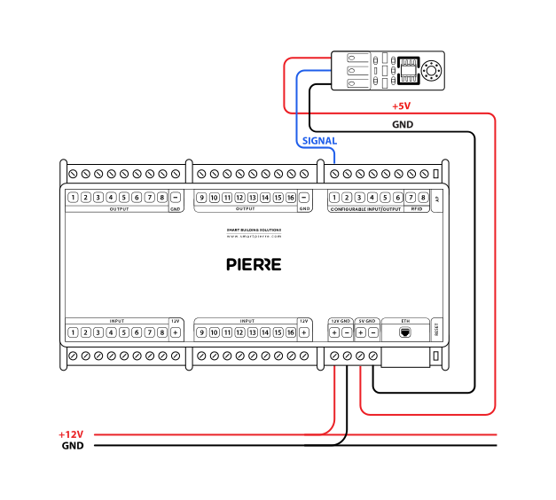
The temperature sensor has three main pins: Power +, Power –, and Output.
The Power + pin is connected to the controller's 5V output, depending on the sensor's voltage requirement.
The Power – pin is connected to the controller's GND (ground) to complete the power circuit.
The Output pin is wired to one of the controller’s analog input pins for reading temperature data.
| Run | Wires | Cross-section | Cable type | Conductors |
|---|---|---|---|---|
| From temperature sensor to PIERRE Controller | 3 | 0.2 mm² (24 AWG) | Cat 5 U/UTP | +5 V, GND, SIGNAL |
One run, three conductors: 5 V, ground and signal. A single Cat 5 U/UTP cable carries it — three of its eight conductors are used, the rest left spare. Maximum length 100 m. Do not run the data cable alongside high-voltage cable.
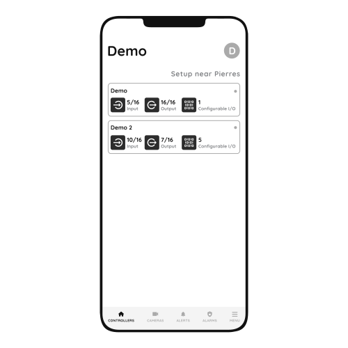
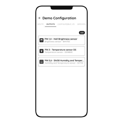
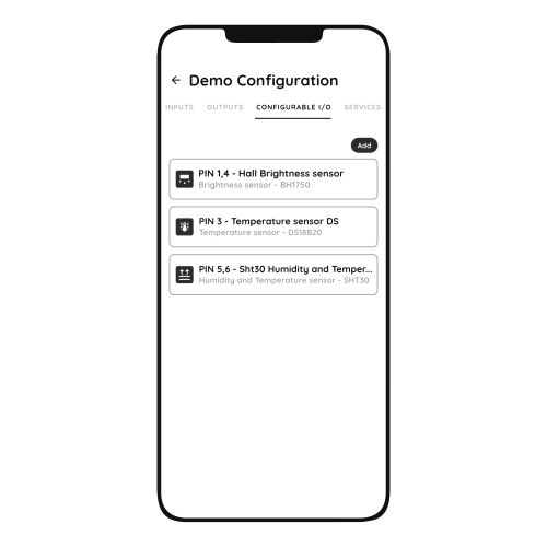
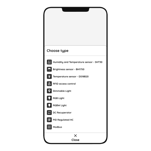
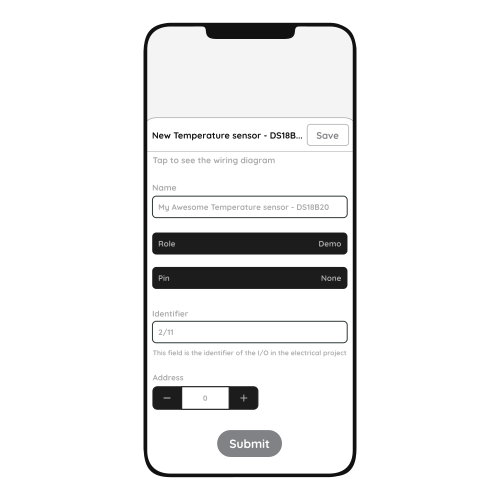
For more details follow next steps.
To confirm your choice tap Submit and Save.
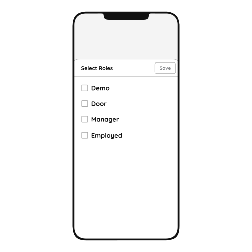
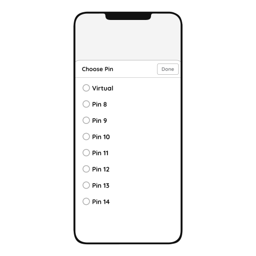
Wiring and commissioning the wired temperature sensor. https://www.youtube.com/watch?v=30_4cPK_UmE
Temperature sensor: wiring and configuration, part 2. https://www.youtube.com/watch?v=ZwX1gah_huc
Check GND, +5 V and the data conductor at the controller. The supply must be +5 V; if the polarity is reversed, swap it.
Trace them with an acoustic wire detector and tone generator.
Only other DS18B20 sensors, each with its own address. Remove anything else from that Configurable I/O pin.
Measure at the sensor end between GND and 5 V, and between data and GND. Both should read about 5 V. If not, check the wiring.
Confirm the conductors are landed on the controller and that the sensor sits on a Configurable I/O pin, not on a 12 V input. Wait 5–10 seconds for the first measurement. If nothing appears, move the sensor to another Configurable I/O pin or replace it. If a second sensor is on the same controller, swap them to find out whether the fault is the wire or the sensor.
5 V from the controller.
100 m on Cat 5 U/UTP. Do not run the data cable next to high-voltage cable.
If one input influences an output, both should be added to the same controller. A motion sensor triggering a lamp, for example, performs best when both sit on the same controller.
The Configurable I/O pins on the PIERRE Controller carry digital sensor and control signals, for example the DS18B20 temperature sensor, the BH1750 brightness sensor and 0–10 V control.
At eye level, away from draughts and external walls.
See the Product specifications. Wired and wireless versions are available.
At least one for basic heating or cooling control. In practice, one per zone or room where you want individual control.
Not always necessary, but often useful. Skip it if the sensor is factory-calibrated to ±0.5 °C or better, the application is ordinary comfort heating or cooling, and the mounting position is good. Calibrate if the reading disagrees with a reference thermometer, if the sensor sits where electronics, sunlight or poor airflow affect it, or if the system needs precise control. In the Smart PIERRE app calibration is optional — the offset is there so you can fine-tune it.