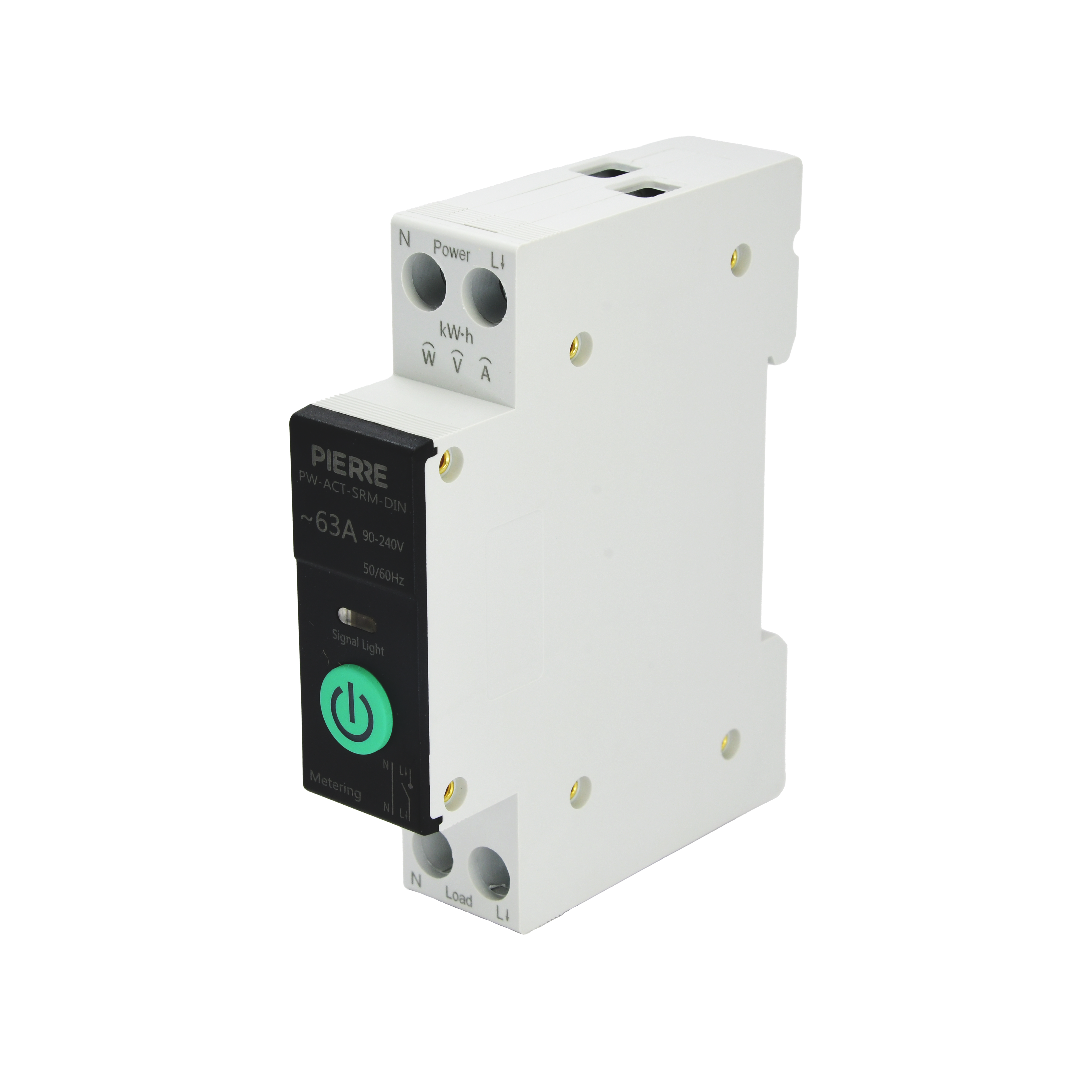
Smart Relay with Electricity Measurement (DIN)
User Manual

Smart Relay with Electricity Measurement (DIN)

SKU: PW-ACT-SRM-DIN
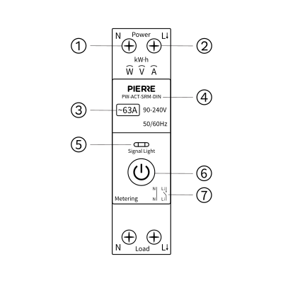
1. Product Description

Image
  1. N Pole
  2. L Pole
  3. Max Adjustable Current
  4. Model Number
  5. LED indicator
  6. Button Switch
  7. Circuit Diagram

2. Product Size

Image

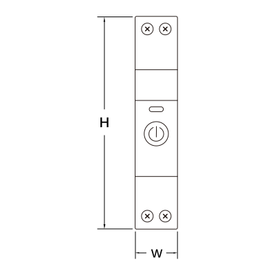
W: 18 mm

H: 82 mm

Image

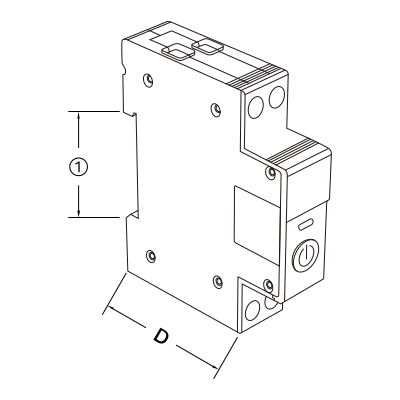
D: 51 mm

  1. 35 mm

3. System requirements

Image

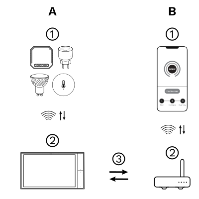
The PIERRE Wave (Zigbee 3.0, 2.4 GHz) system consists of the following components.

Required

  1. PIERRE Wave products: switches, modules, sensors, thermostats and other devices. They connect wirelessly to the gateway.
  2. Gateway: a PIERRE display and/or gateway. It links all PIERRE Wave devices and handles the communication with the app.

Optional

  1. Smart PIERRE app: control and monitoring from a smartphone or tablet. Not required for basic operation.
  2. Router: gives the gateway internet access for remote control.

Operation: the gateway connects to the router by Wi-Fi or LAN. PIERRE Wave products communicate wirelessly with the gateway in both directions: commands are sent and status updates are received through the Smart PIERRE app.

What you need

Zigbee gateway: a PIERRE display and/or gateway. One of those must already be commissioned before the device can be added.
4. Safety Instructions

  • Installation must be performed by a qualified electrician.
  • Always disconnect the mains power supply before wiring or maintenance.
  • Ensure the maximum rated current (63 A) is not exceeded.
  • The relay must be installed in a dry, ventilated environment on a DIN rail.
  • Do not cover the ventilation openings.
  • Comply with local electrical regulations.

5. Installation

Image
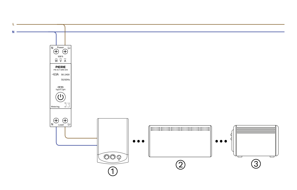
  1. Mount the relay securely on a DIN rail.
  2. Connect L (Live) and N (Neutral) from the mains to the upper terminals marked Power.
  3. Connect the load (e.g. water heater, convector, radiator) to the lower terminals marked Load.
  4. N → Neutral to the load
  5. L → Live to the load
  6. Tighten all screws and verify the connections.
  7. Switch on the mains power and check the LED indicator.

Diagram reference:

  1. Water heater
  2. Convector heater
  3. Radiator

6. LED Indicator Description

Image

The LED indicator flashing blue indicates the device is in pairing mode.

Image

The LED indicator solid blue shows the switch is on.

Image

The LED off indicates the switch is off.

7. Cable and wiring

Run Wires Cross-section Cable type Conductors
From distribution board to smart relay 2 1.5 mm² NYM-O L, N
From smart relay to load 2 1.5 mm² NYM-O L, N

Two runs, two conductors each. The first brings the supply from the distribution board into the relay; the second carries the switched output from the relay to the load. Both are line and neutral only — no signal wire, because the relay is commanded over Zigbee rather than by a physical input.
8. App-to-Device Pairing

Image

Please scan the QR code to download PIERRE application
Image

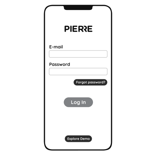
Log in with your Username and Password
Image

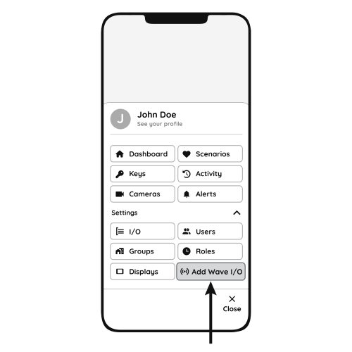
Open Settings and press "Add Wave I/O"
Image

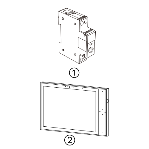
Press and hold the Button Switch for 10 seconds until the Indicator Light starts flashing
  1. Smart Relay
  2. PIERRE Wave Gateway 
Image

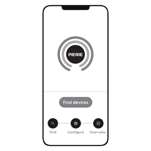
Press "Find Devices"

Image

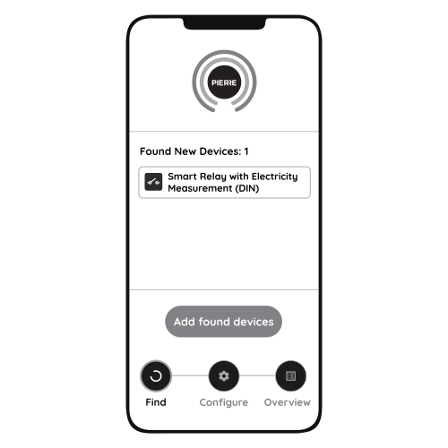
PIERRE application will show the list of available devices. Press "Add found devices"
Image

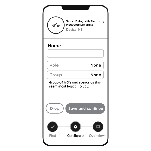
Enter Name, Role and Group settings and Save it
Image

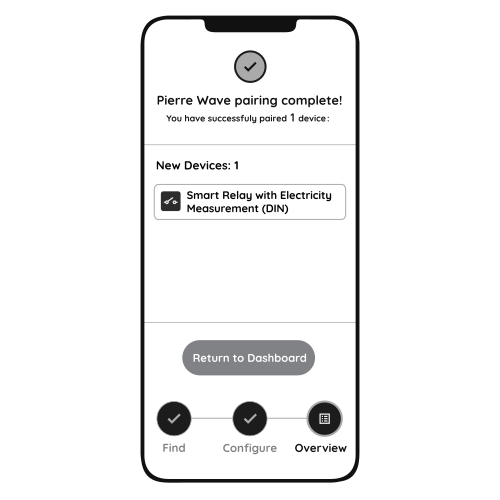
When the Light indicator stops flashing, the PIERRE Wave pairing process is finished