User Manual
Radiator Valve (TRV)
SKU: PW-ACT-TRV
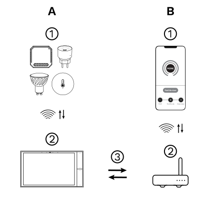
The PIERRE Wave (Zigbee 3.0, 2.4 GHz) system consists of the following components.
Required
Optional
Operation: the gateway connects to the router by Wi-Fi or LAN. PIERRE Wave products communicate wirelessly with the gateway in both directions: commands are sent and status updates are received through the Smart PIERRE app.
Zigbee gateway. The valve joins the Zigbee network through a PIERRE display acting as gateway or through The One gateway. One of those must already be commissioned before the valve can be added. Requires 2x 1.5V AA batteries.
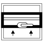
Open window function
If an open window causes the room temperature to drop by more than 6 °C within 4 minutes, the screen shows "OP" and the valve closes. The state is cleared when the room temperature rises by 3 °C, automatically after 48 minutes, or manually.

Anti-scale function
If the valve stays partially closed or unused for a long time, deposits can block it. To prevent this, the valve head fully opens the valve every two weeks for 30 seconds. During this cycle the screen briefly shows "Ad" and then returns to normal operation.
Child lock function
To prevent accidental adjustments by children, activate the child lock function by pressing and holding the button when the device is powered on. The screen will show "LC" to indicate activation. To unlock, simply repeat the activation process.

Anti-freezing
When the valve is switched off ("OFF" on the screen) the anti-freeze function is active: the valve opens when the room temperature drops below 5 °C and closes when it rises above 8 °C.

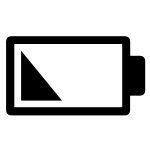
Low voltage warning function
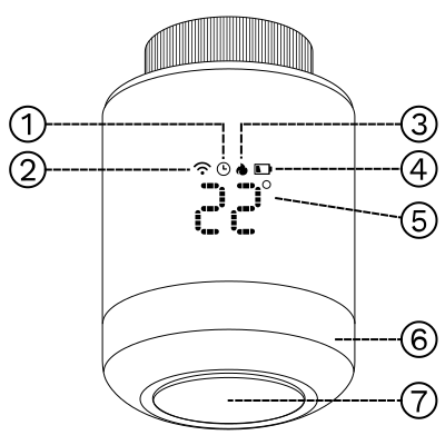
When the battery voltage is too low, an alarm symbol will appear on the display to remind the user to replace the battery.
Temporary mode
When in programming mode, if you want to manually change the temperature of the current programming period, turn the knob to adjust the desired temperature, which will be maintained until the end of the current programming period.
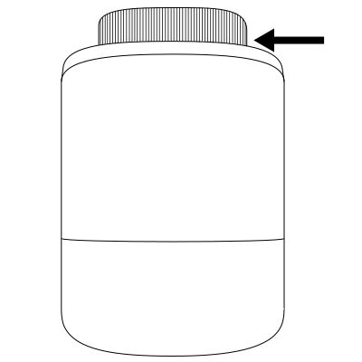
Press down on the bottom cover and unscrew it to the right.
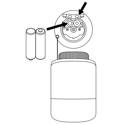
Press and hold the battery sheet and push it out, placing the battery in the compartment.
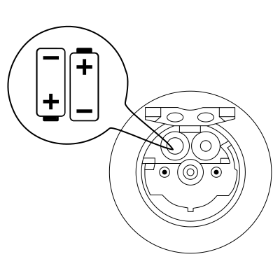
NOTE
Insert the battery according to the "+" and "-" marks in the battery compartment.
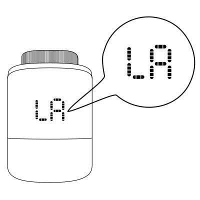
The screen shows "LA".
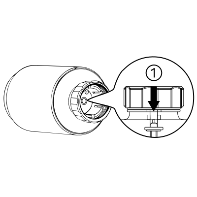
Set the temperature to the maximum of 35 °C (when the top bar is flush with the bottom).
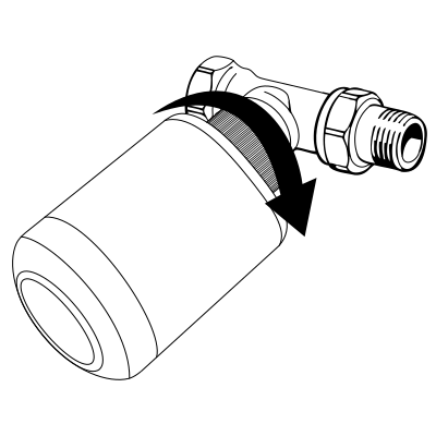
Rotate and tighten the copper ring of the valve head onto the thread of the radiator valve.
Note: if the valve connection does not match the valve head, install the matching adapter first (see Accessories).
The following adapters are available for mounting the radiator valve (TRV):
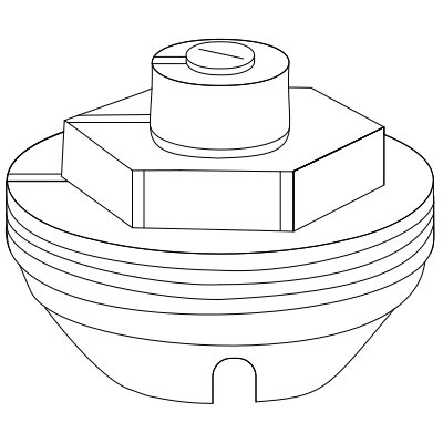
Danfoss RA Adapter
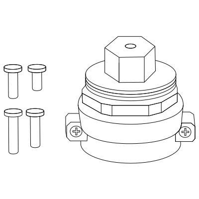
Danfoss RAVL Adapter
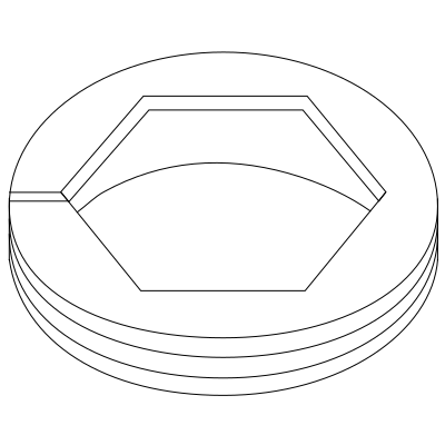
Danfoss RAV Adapter
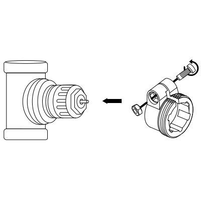
Giacomini Connector Adapter
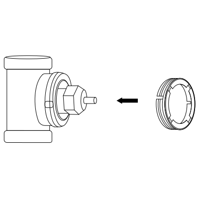
M28 × 1.5 Connector Adapter
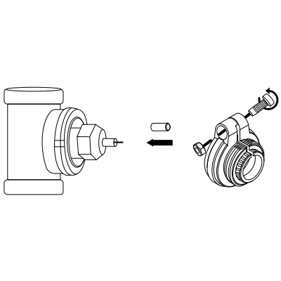
Caleffi Connector Adapter
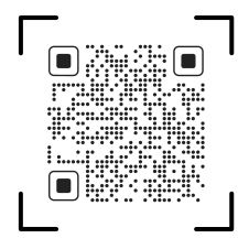
Please scan the QR code to download PIERRE application
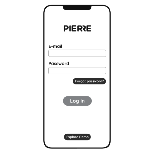
Log in with your Username and Password
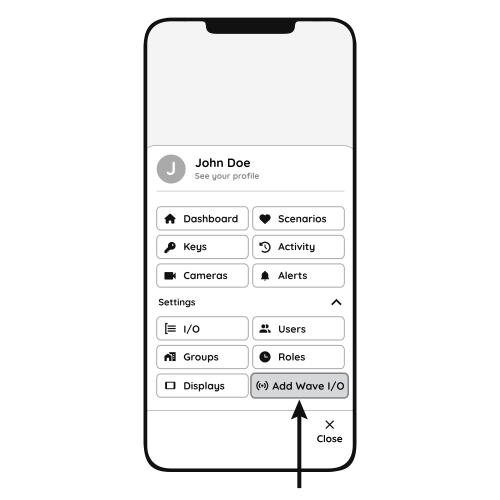
Open Settings and press "Add Wave I/O"
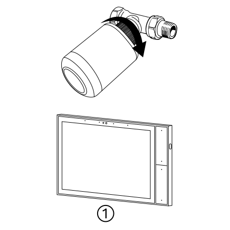
Turn the knob to the "OFF" state, press and hold the button for 5 seconds; the wireless icon on the screen will flash.
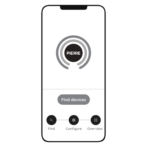
Press "Find Devices"
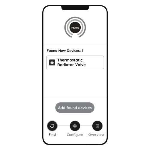
PIERRE application will show the list of available devices. Press "Add found devices"
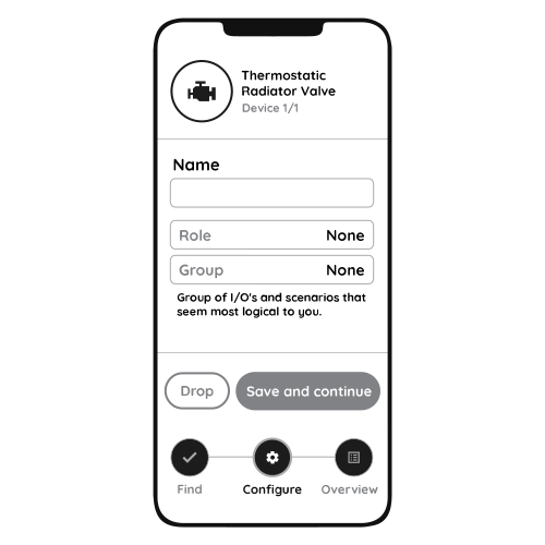
Enter Name, Role and Group settings and Save it
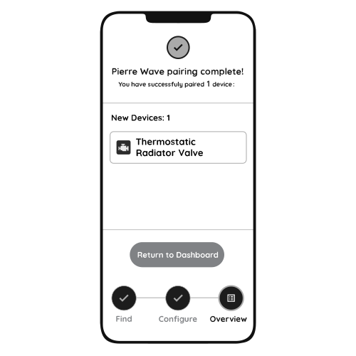
When the wireless icon stops flashing, the PIERRE Wave pairing process is finished.