Gate Opener Module
User Manual

Gate Opener Module

SKU: PW-MOD-GO
1. Product Description

Image
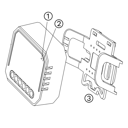
  1. Reset Key
  2. Indicator Light
  3. Mounting Clip

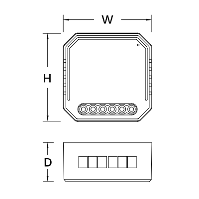
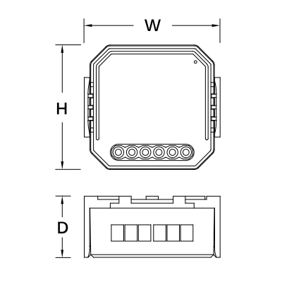
2. Product Size

Image
  • Without Mounting Clip
    • W: 46 mm
    • H: 46 mm
    • D: 18 mm
Image
  • With Mounting Clip
    • W: 50 mm
    • H: 46 mm
    • D: 22.5 mm

3. System requirements

Image

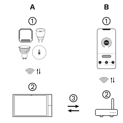
The PIERRE Wave (Zigbee 3.0, 2.4 GHz) system consists of the following components.

Required

  1. PIERRE Wave products: switches, modules, sensors, thermostats and other devices. They connect wirelessly to the gateway.
  2. Gateway: a PIERRE display and/or gateway. It links all PIERRE Wave devices and handles the communication with the app.

Optional

  1. Smart PIERRE app: control and monitoring from a smartphone or tablet. Not required for basic operation.
  2. Router: gives the gateway internet access for remote control.

Operation: the gateway connects to the router by Wi-Fi or LAN. PIERRE Wave products communicate wirelessly with the gateway in both directions: commands are sent and status updates are received through the Smart PIERRE app.

What you need

A PIERRE Wave (Zigbee 3.0, 2.4 GHz) gateway: a PIERRE display and/or gateway.

4. Product specifications

Technical Specifications

Connectivity

Connectivity Zigbee
Communication Frequency 2.4GHz - 2.484GHz

Features

LED Indicators Yes
Operation Range 200 m

Environmental

Operating Temperature +14°F - +104°F
Operating Temperature (°C) -10 - +40
Operating Humidity ≤ 80 % RH
IP Rating IP20

Electrical

Power Supply 100-240V AC 50-60Hz

Safety

Safety Features Overload protection, Over voltage protection, Short circuit protection, Thermal protection, Electrostatic protection, Surge protection

Control

Number of Channels 1 channel

Physical

Panel Material ABS+PC material
Product Color White
Wiring Requirements N - Neutral, L - Line

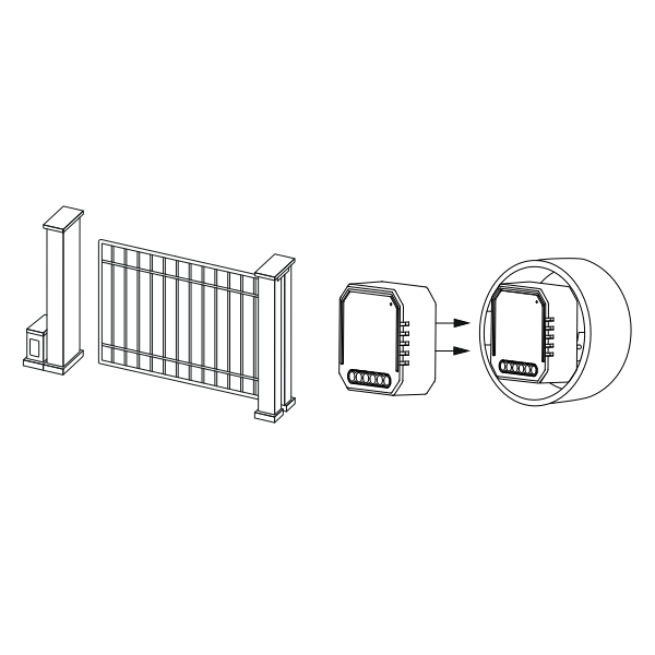
5. Installation

Image

Warnings:

  • Installation must be carried out by a qualified electrician in accordance with local regulations.
  • Keep the device out of reach of children.
  • Keep the device away from water, damp or hot environments.
  • Install the device away from strong signal sources such as microwave ovens that may cause signal interruption resulting in abnormal operation of the device.
  • Obstruction by concrete wall or metallic materials may reduce the effective operation range of the device and should be avoided.
  • Do NOT attempt to disassemble, repair or modify the device.

6. Wiring Instructions and Diagrams

  1. Turn off the power supply before carrying out any electrical installation work.
  2. Connect wires according to the wiring diagram.
  3. Insert the module into the junction box.
  4. Turn on the power supply and follow the gate opener module configuration instructions.

Note: During pairing keep the module within range of the PIERRE Wave gateway.
Image

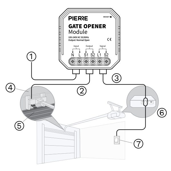
The diagram shows the typical wiring of the PIERRE Gate Opener Module. Numbered components:

  1. Input AC power (L + N): the module is powered from 100–240 V AC. Connect line (L) and neutral (N) as shown; this supplies the control electronics and the relay.
  2. Input – contact sensor (S1, S2): connect a magnetic contact sensor fitted to the gate or garage door. It reports whether the gate is open or closed.
  3. Fixed sensor part (wall-mounted): the part of the magnetic contact fixed to the wall or frame. It stays in place and aligns with the moving part when the gate is closed.
  4. Moving sensor part (gate-mounted): the magnet mounted on the gate or door. It moves with the gate and closes the contact when it meets the fixed part (3).
  5. Door control terminals L1 and L2: a dry-contact relay output that gives a short pulse to the motor's trigger input, like a press of the wall push-button. Connect it to the gate motor's push-button (start) terminals.
  6. Gate motor unit: receives the pulse from L1/L2 and opens or closes the gate.
  7. Manual wall push-button: a push-button wired in parallel with L1 and L2. Pressing it triggers the motor in the same way as the module.
Run Wires Cross-section Cable type Conductors
From electric box to gate opener module 2 1.5 mm² NYM-O L, N (230 V AC)
From gate opener module to gate motor (trigger input) 2 0.75 mm² H07V-K Relay output L1, L2
From gate opener module to push-button 2 0.75 mm² H07V-K L1, L2 (in parallel with the motor trigger)
From gate opener module to contact sensor 2 0.75 mm² H07V-K Sensor input S1, S2

Four runs, two conductors each. The 230 V supply arrives on 1.5 mm² NYM-O. The three signal runs are single-core flexible: 0.75 mm² to the gate motor's trigger input, 0.75 mm² to the push-button, and 0.75 mm² to the contact sensor that reports whether the gate is open or closed. Only the supply run carries mains; the other three are low-voltage signalling.

7. Manual Override

A wall push-button wired in parallel with the L1 and L2 output terminals triggers the gate motor directly, so the gate can be opened or closed without the app.

Notes:
  1. The module output is a momentary dry contact; it does not hold the gate open or closed.
  2. The contact sensor on S1 and S2 reports the open/closed state to the app whichever way the gate was triggered.

8. App-to-Device Pairing

Image

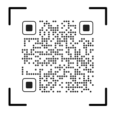
Please scan the QR code to download PIERRE application
 

Image

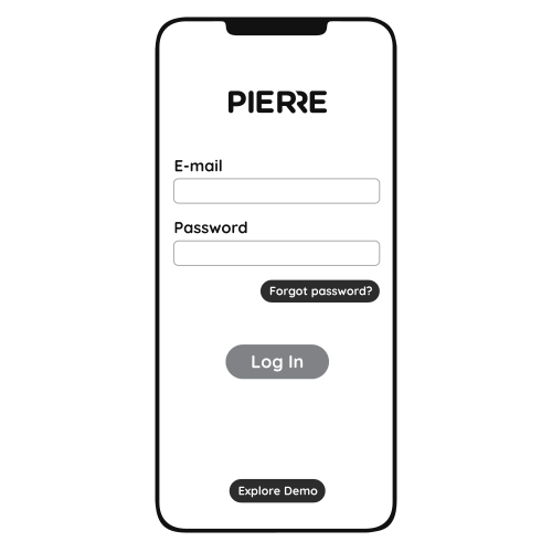
Log in with your Username and Password
 

Image

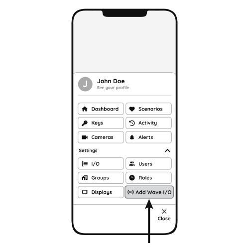
Open Settings and press "Add Wave I/O"
 

Image

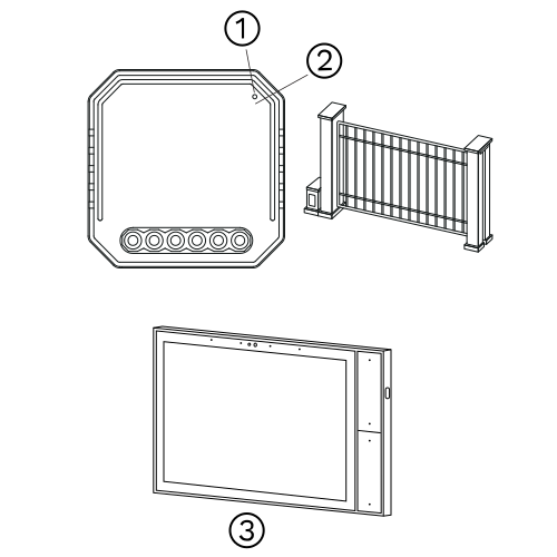
Press and hold the Reset Key for 10 seconds (use a small, thin object like a paperclip) until the Indicator Light starts flashing
  1. Indicator Light
  2. Reset Key
  3. PIERRE Wave Gateway
Image

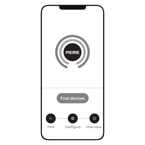
Press "Find Devices"
 

Image

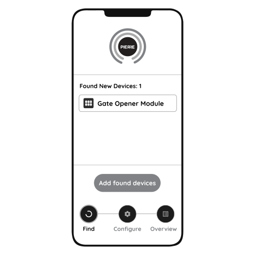
PIERRE application will show the list of available devices. Press "Add found devices"
 

Image

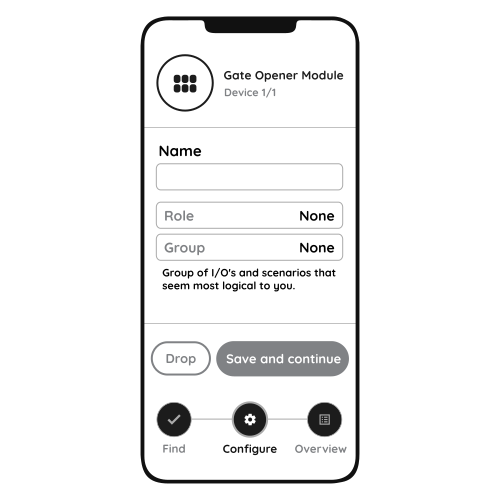
Enter Name, Role and Group settings and Save it
 

Image

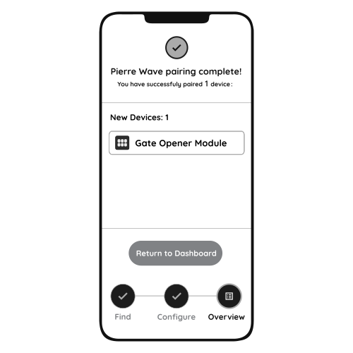
When the Light indicator stops flashing, the PIERRE Wave pairing process is finished
 

9. FAQ

Q1: What should I do if I cannot configure the gate opener module?

  • Check that the module is powered.
  • Make sure the PIERRE Wave gateway (PIERRE display and/or gateway) is online.
  • Check the wiring against the diagram.

Q2: What can be connected to this module?

Gate and garage door motors with a push-button (dry contact) trigger input, plus a magnetic contact sensor for open/closed feedback.

Q3: What happens if the Wi-Fi or internet goes down?

The gate can still be operated with the wall push-button and from the PIERRE display and/or gateway; only remote access from the app is unavailable.

Q4: How do I reset the module?

Press and hold the reset key for about 10 seconds until the indicator light flashes quickly.