User Manual
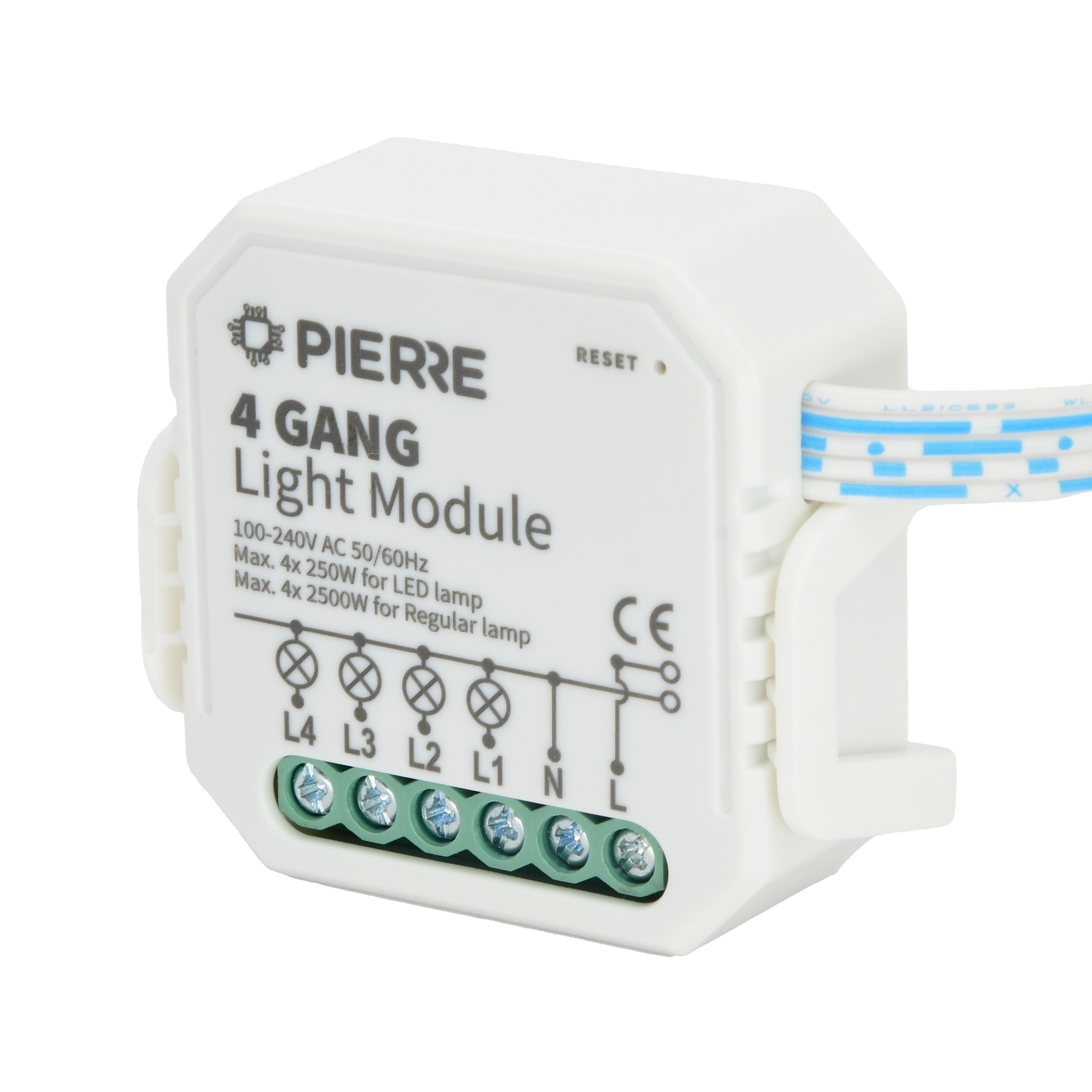
4 Gang Light Module (L+N)
SKU: PW-MOD-L-4G-NL
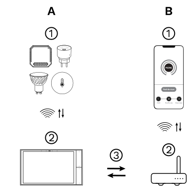
The PIERRE Wave (Zigbee 3.0, 2.4 GHz) system consists of the following components.
Required
Optional
Operation: the gateway connects to the router by Wi-Fi or LAN. PIERRE Wave products communicate wirelessly with the gateway in both directions: commands are sent and status updates are received through the Smart PIERRE app.
A PIERRE Wave (Zigbee 3.0, 2.4 GHz) gateway: a PIERRE display and/or gateway.
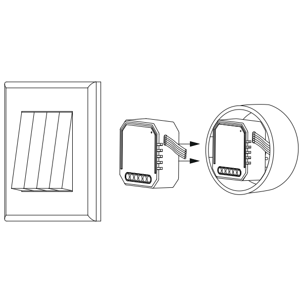
Warnings:
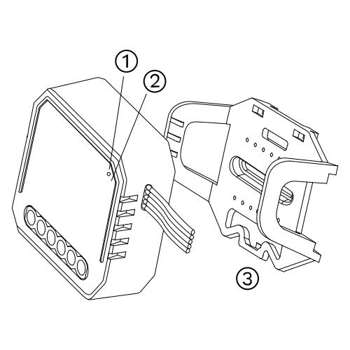
The switch module terminal reserves the access of manual override function for the end-user to switch on/off.
Notes:
Note: During pairing keep the module within range of the PIERRE Wave gateway.
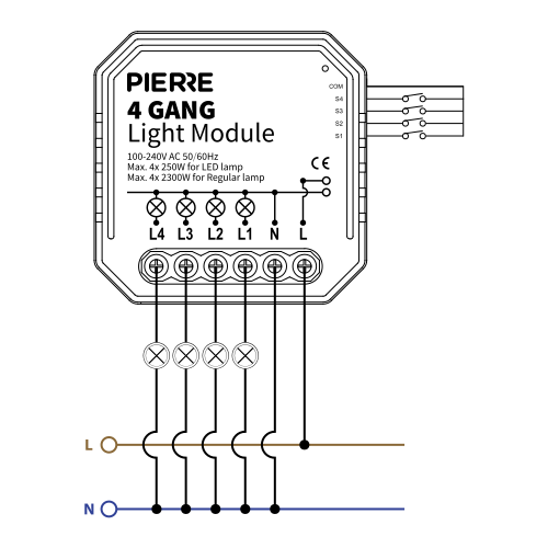
With 1 normal switch
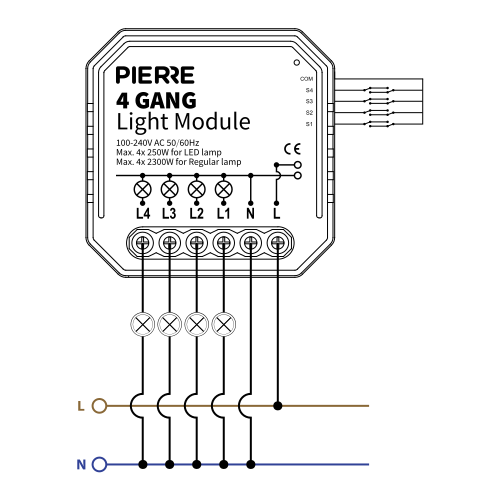
With 2 normal switches
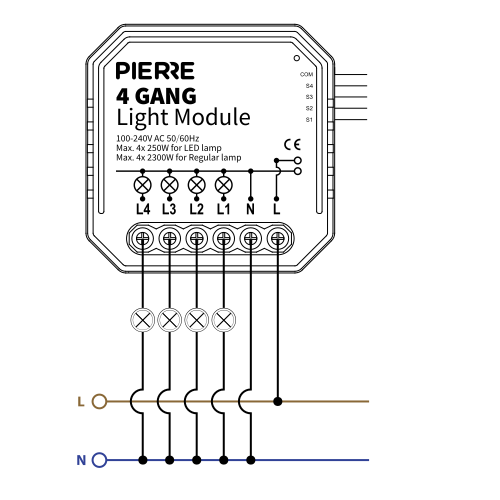
Without normal switch
| Run | Wires | Cross-section | Cable type | Conductors |
|---|---|---|---|---|
| From electric box to light module | 2 | 1.5 mm² | NYM-O | L, N |
| From light module to light fittings | 5 | 1.5 mm² | NYM-J | L1, L2, L3, L4, N |
| From light module to switches | 5 | 0.75 mm² | NYM-J | COM, S1, S2, S3, S4 |
Three runs. The supply into the module is two conductors at 1.5 mm², line and neutral. Out to the fittings: 4 switched lines (L1–L4) plus the neutral at 1.5 mm², one switched line per fitting. The wall switches are looped on 0.75 mm²: common and S1–S4, one input per gang. Because the neutral is present at the module, this variant also works as a Zigbee repeater.
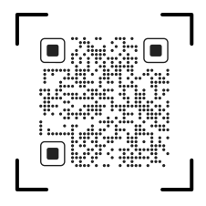
Please scan the QR code to download PIERRE application
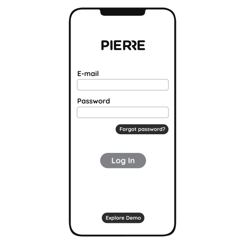
Log in with your Username and Password
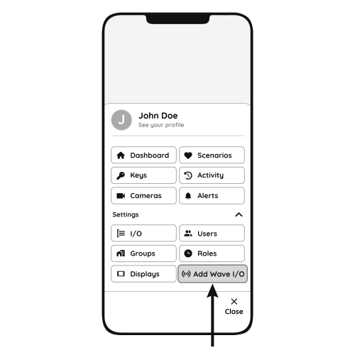
Open Settings and press "Add Wave I/O"
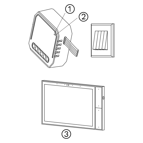
Press and hold the Reset Key for 10 seconds (use a small, thin object like a paperclip) until the Indicator Light starts flashing
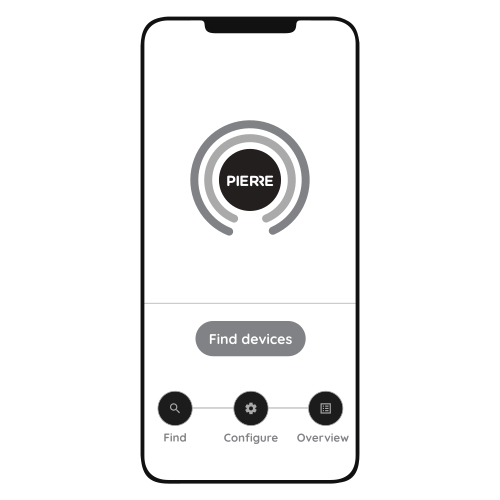
Press "Find Devices"
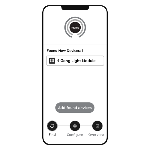
PIERRE application will show the list of available devices. Press "Add found devices"
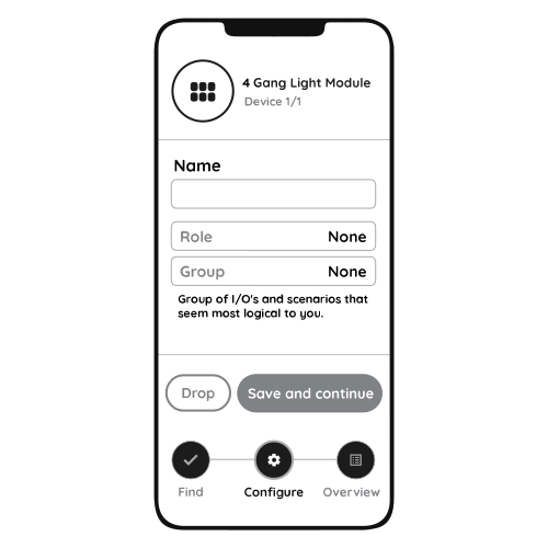
Enter Name, Role and Group settings and Save it
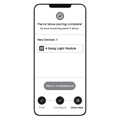
When the Light indicator stops flashing, the PIERRE Wave pairing process is finished
Lighting loads such as ceiling lamps and panel lights, within the rated load given in the specifications.
The module keeps working locally. You can still switch the light with the wall switch and control it from the PIERRE display and/or gateway; only remote access from the app is unavailable.
Either toggle the connected wall switch 5 times, or press and hold the reset key for about 10 seconds, until the indicator light flashes.
The module keeps its last state and comes back when power is restored.
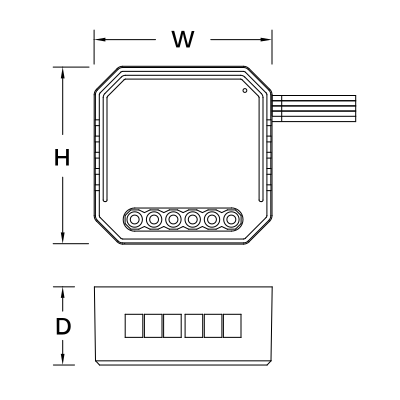
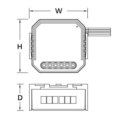
See the Product Size section. The module fits behind the switch in a standard wall box; a deep box makes wiring easier.
Modules with a neutral also act as Zigbee repeaters and strengthen the network. Use the no-neutral module where no neutral is available at the switch.
Yes. Any standard wall switch or push-button can be connected to the S inputs.
Yes. See the diagrams in the Wiring Instructions and Diagrams section.